
I’m looking at an Electro-Fashion sewable PICAXE control board from Kitronik. There are a few wearable systems now that keep getting better and are getting easier to use and help people get started with so this was great to see another system. One huge advantage of being low cost (just over a fiver) that it’s a great way to get a system prototyped. You can get up and running within an hour even with no previous knowledge or experience.
Prototyping
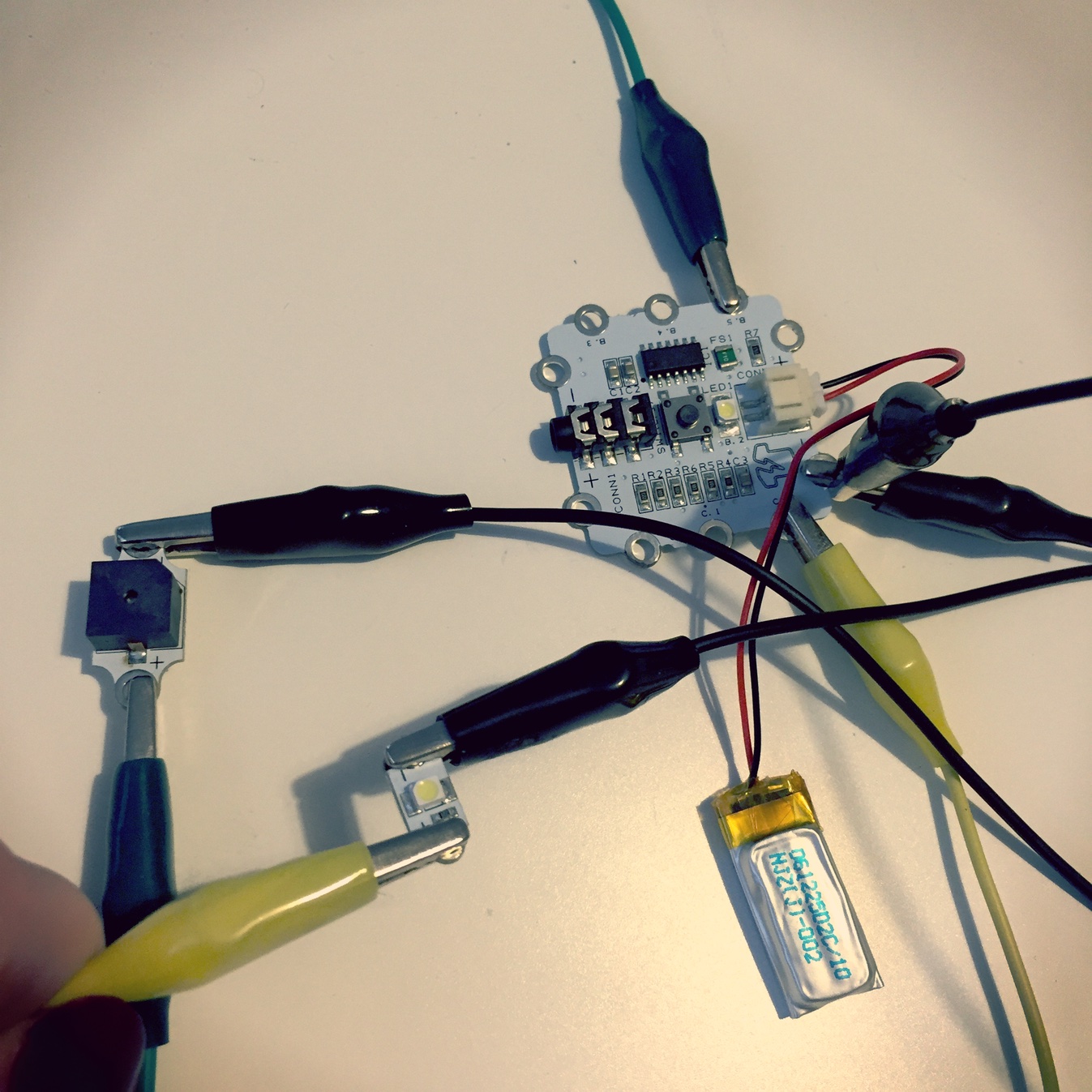
If you get a few basic components such as the main board, LEDs, switch, and maybe some sensors and you’ll have enough to get started. You’ll need a USB download cable too which will be the biggest initial cost (but still only £11.95) which you will be using with all PICAXE boards to download the program directly to the chip. You also need a power source!
To prototype quickly and test out what you can do, you need some form of clips / crock clips / connectors to make the connections to the I/O ports.
Map out your circuit
Once you have done your prototyping phase, you can then be sure to have some conductive thread and can sew your creation! I always map out my circuit on felt or similar with a marker etc with colours for different connections so you are sure to not cross lines and make the most effective circuit, and sew it to that before sewing the completed work on to my final fabric. (Or integrating the felt version.)
My first stop was to look at the resources out there for using this platform. I went to the getting started guide at PICAXE
If you are getting one of the electro-fashion boards from Kitronik you’ll see on the product page details that there are links to accessories that you can use with this system, (which are also usable with other systems so you don’t have to keep to just one board type).
Have a look also at the guide from Kitronik about getting started. It’s easy to follow and guides you to getting the software / drivers and using the board. Note that this is for Windows though!
So… this is a board that I have never used before and a new system to me. I have no experience with PICAXE. If you are the same then hopefully I will have made a bit of a mess with it so that you can go through it a little more smoothly.
I’m on a Mac, so I grabbed the Mac version of Blockly which I choose the browser-based one, but have a look at the downloads page for your own system.
Picaxe & COM ports
Once I opened it, you need to select the PICAXE type and COM port, this is how we can communicate with the board. It will let us put the code onto the chip when we are ready.
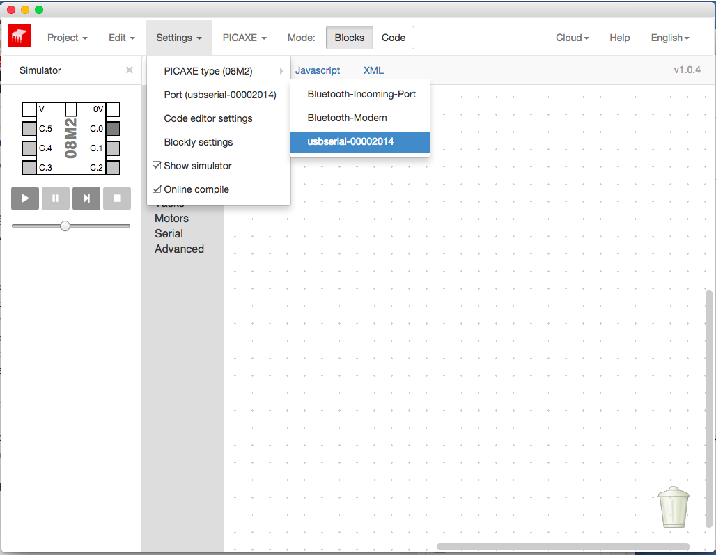
You may need to look up your PICAXE type, and there is a handy little menu item that does the checking for you:
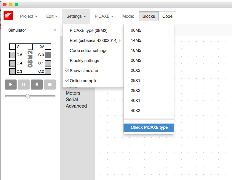
Mine works with 14M2 selected.
Oops! Note at the time of doing this, I am a little unclear if the connector also powers the board at this phase and if I should plug in a power source? I was looking at this board and trying it out and had a friend describe to me what I was doing. They think there is no power. So I’ll plug in the power as well.
The board can now be found with the software so do plug in your power folks!
Using the blocks to generate code is straightforward once you know what to do.
Pins to use
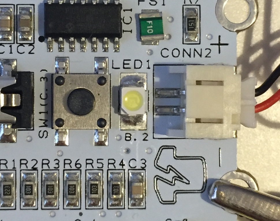
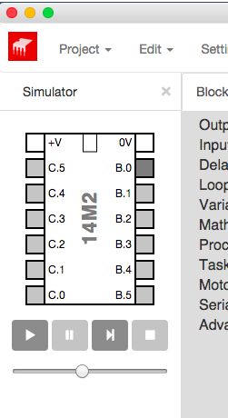
Using the menu on the left, drag on to the main area the things you’d like the board to do. Looking at the board, make a note of the pins (the output or input) on the board. On my board they are noted as B.5 B.4 B.3 the LED is on B.2 C.0 C.1 and C.4. There are also 2 areas to connect power to the board (as well as the LiPo connector).
The programming blocks I selected will be to make the LED integrated on the board flash on and off.
Program
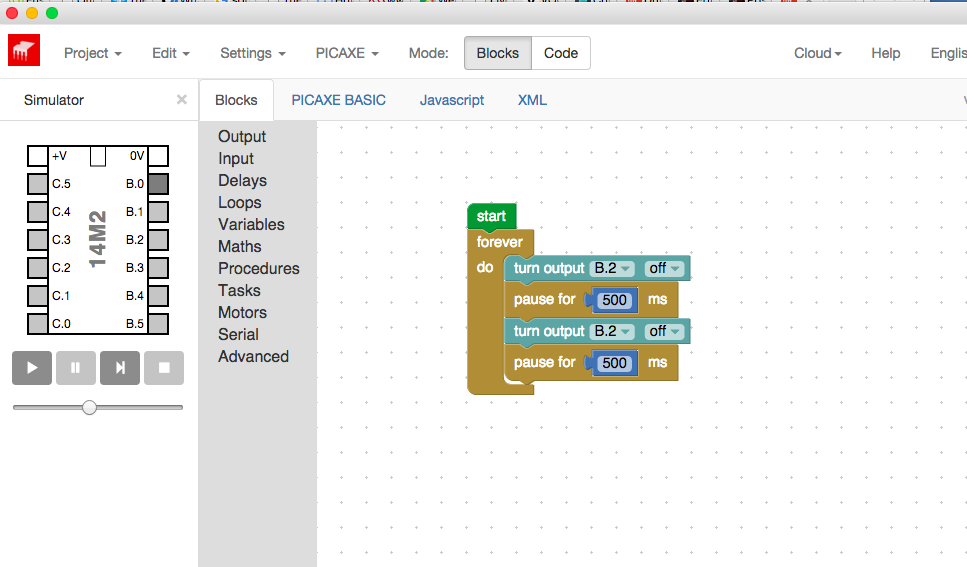
To program using Blockly, use the menu items on the left and drag the ‘blocks’ that you want to use. Put the block directly under the “start” block… match them up (have a look at the accompanying image). Look at the LED blocks there in the blocks required, from the OUTPUT menu. Then run the simulator to be sure it is doing what you want it to.
Running the simulator using the controls just below the ‘chip’ you will see which output pin will be active in your program.
Checking the program on the Picaxe
Using the > play button you can look at how your program is running. When you’re happy with it you need to program your board.
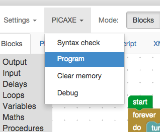
To program the chip when you are happy with what you have written go to the PICAXE menu and select PROGRAM
So that is just a quick whip through of what I did to have a play with this system.
Look through the program to see some of the things you can put together. Then all that’s left is to map out some ideas & thoughts for what you would like to sew together and what you’d like to make! Have fun with it!
The Board that I used Features:
- Built in PICAXE 14M2 programmable IC.
- On-board dimmable white LED.
- On-board switch.
- 6 sewable I/O pins.
- JST connector and sewable ‘+’ and ‘-‘ pads.
- 3.5mm stereo jack for programming.
- Low profile and compact size.
(Note for schools or if you are buying a few of these boards for your projects you can get 10 for as low as £5.70 each)
Progress to learn how to use the Picaxe?
Once downloaded / looked at the software and read up about the board and generally what to do, you can make progress within an hour if you come to it with no previous knowledge at all.
This is a very easy intro to wearables. The connectors are big and sturdy enough to get a good connection for people new to this platform. That alongside the easy ‘blocks’ for programming might be a really good way to get started with wearables!