information
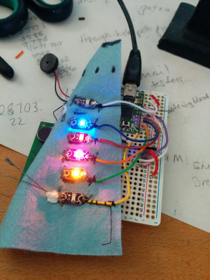
This is a guide that brings together a series of guides and information I discovered when looking for fun projects. It uses deadbugging to create a stand-alone functioning circuit. This is based on the beautiful project on Tinker Log for a ‘geeky advent’. It’s my first circuit sculpture!
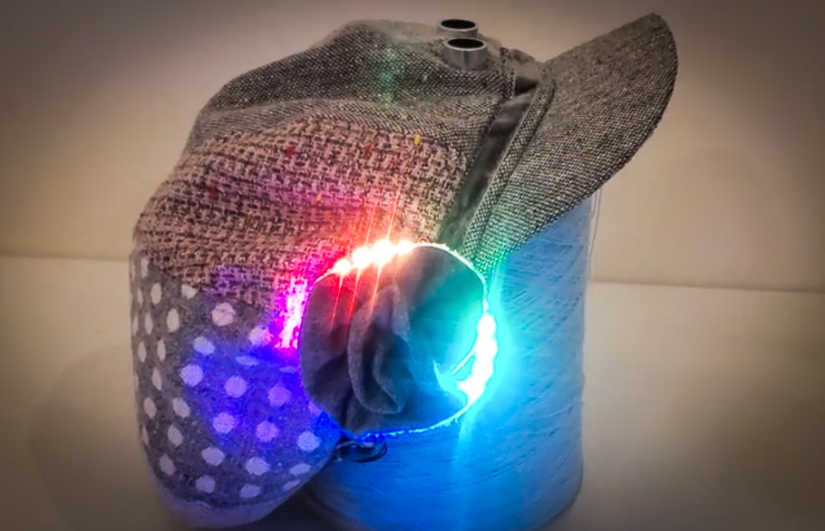
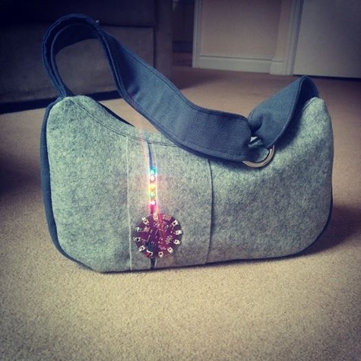
I will be making this flickering lights, light-activated, to put in a forest area nearby where I live, to give it to other walkers in the area, that will be seen at night. It is a very low light so will not disturb the environment. I’m going to modify it to add a little solar panel to keep the battery charged so it should last for a very long time!
the Project
The deadbugging project as detailed on Tinker Log is a great starting point. Have a look at the circuit and how they’ve reduced it to it’s simplest of parts. They also have code provided and reference other sites that have similar circuits. A good place to start your deadbugging journey!
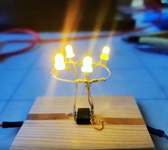
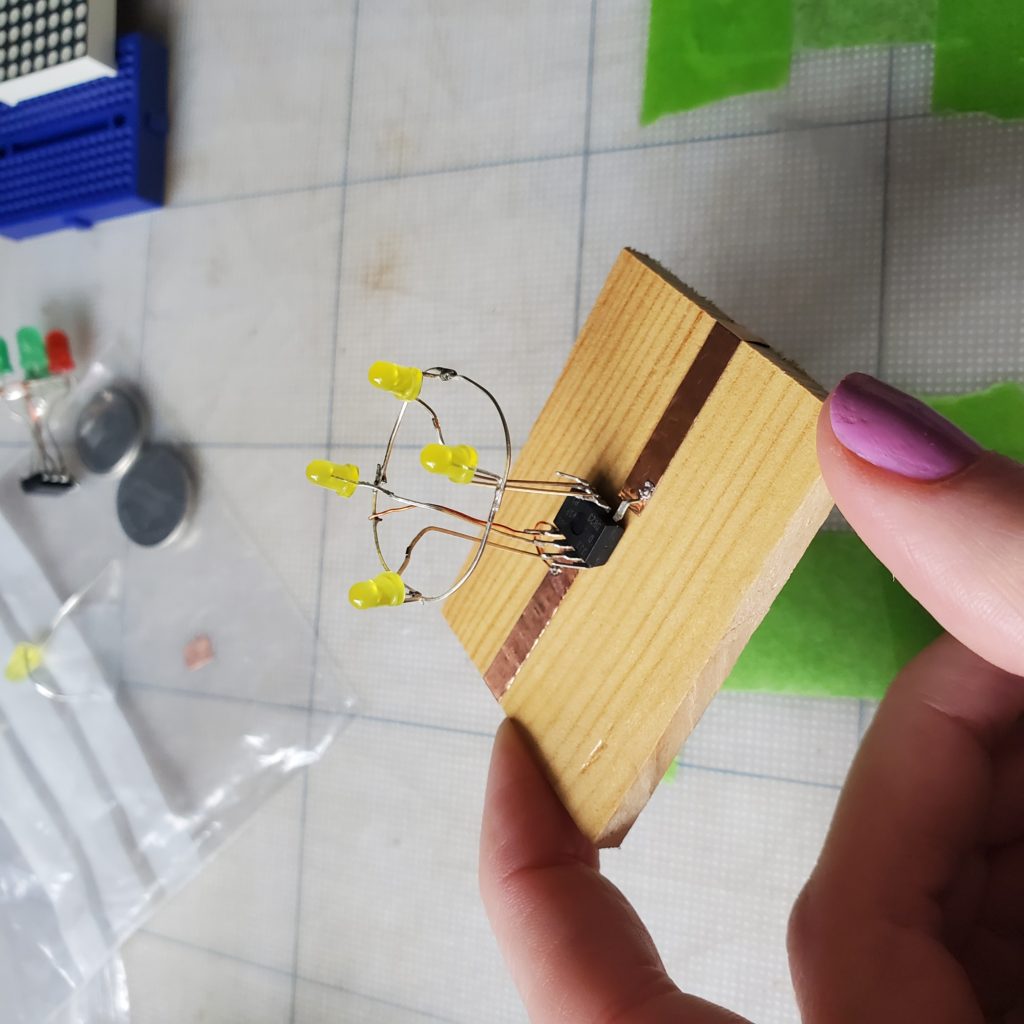
The function is to have a small all-in-one flickering circuit. It is programmed on an ATtiny and runs off a small coin cell battery. One of the LEDs is also used to sense the amount of light, and when it is dark, this circuit produces the flickering light effect.
The circuit and code we are building as on Tinker Log:
“The nice thing about this circuit is, that it needs no special components to detect darkness. It uses an LED for that. An LED is also a photodiode that can detect light of the same wavelength it emits. See here for more details. Sprite ( Sprite’s minimalistic version ) used an available ADC of the ATtiny13 instead of the “Reverse Bias” method.”
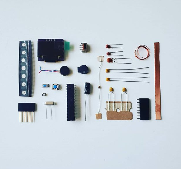
component list
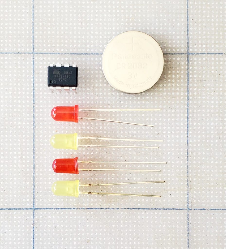
- ATtiny13 (or 25/45/85 etc)
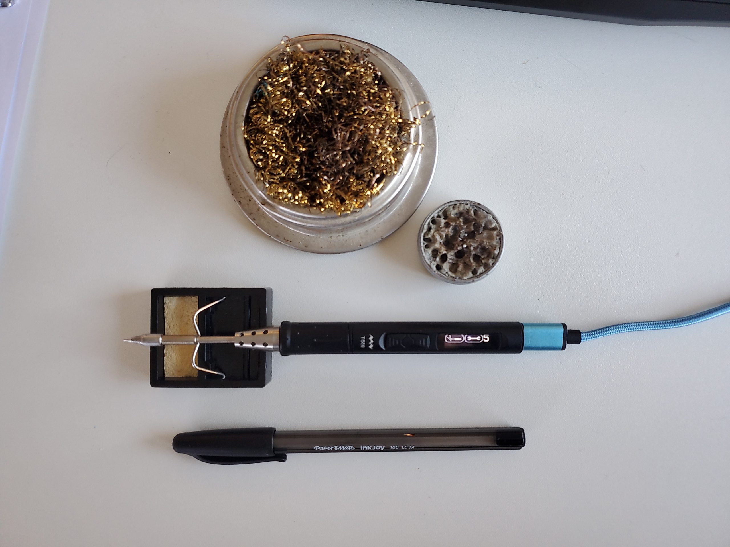
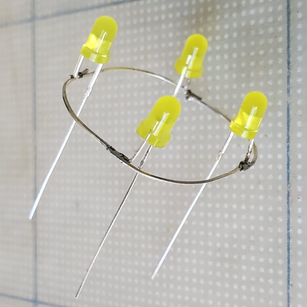
- 4 LEDs use 3mm (not 5mm as shown in the photo)
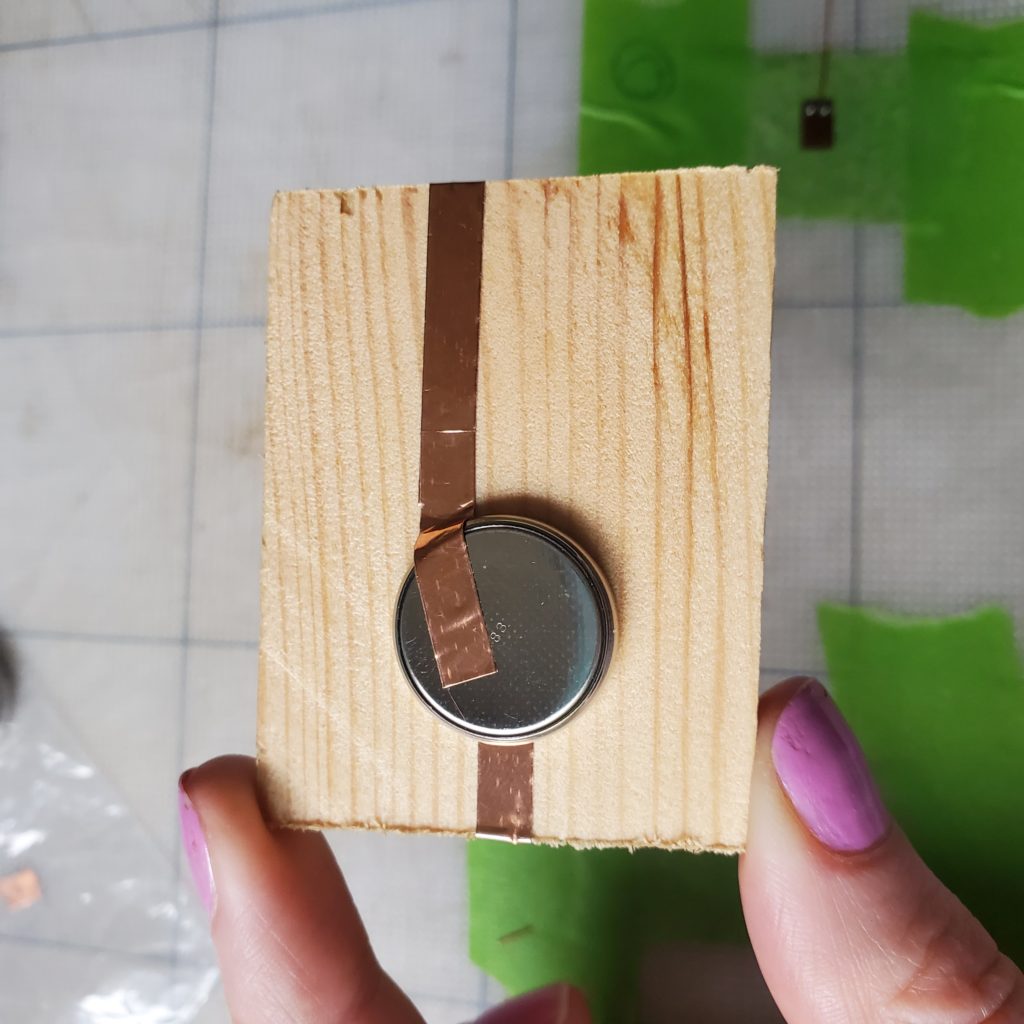
- 3V Coin Cell Battery CR2032 (230 mAh)
- extra wire (I used enamelled copper wire)/ mounting method
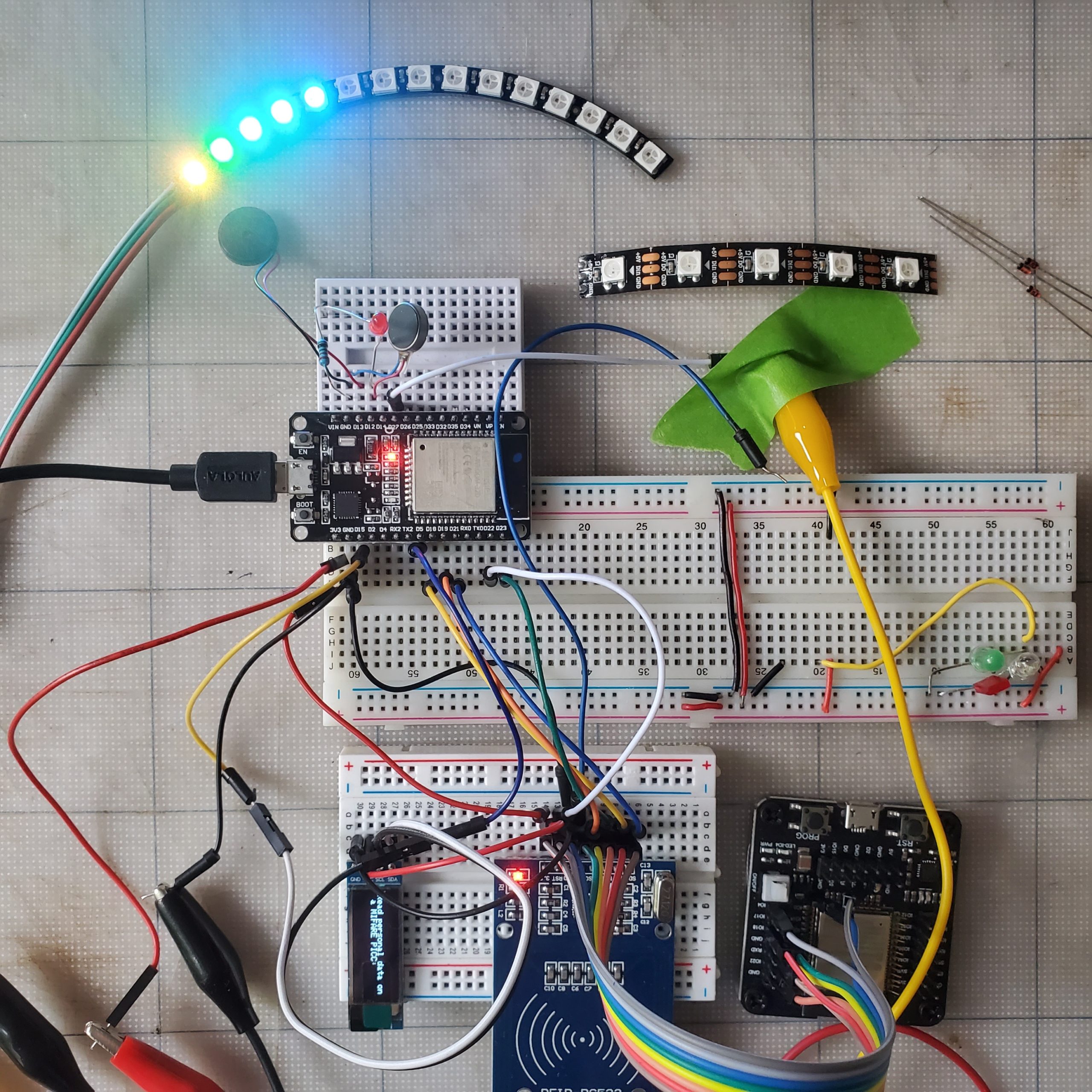
A simple component list, this can be made very cheaply! (and would make fun gifts for people). A video of my deadbugging attempt.
ATtiny details
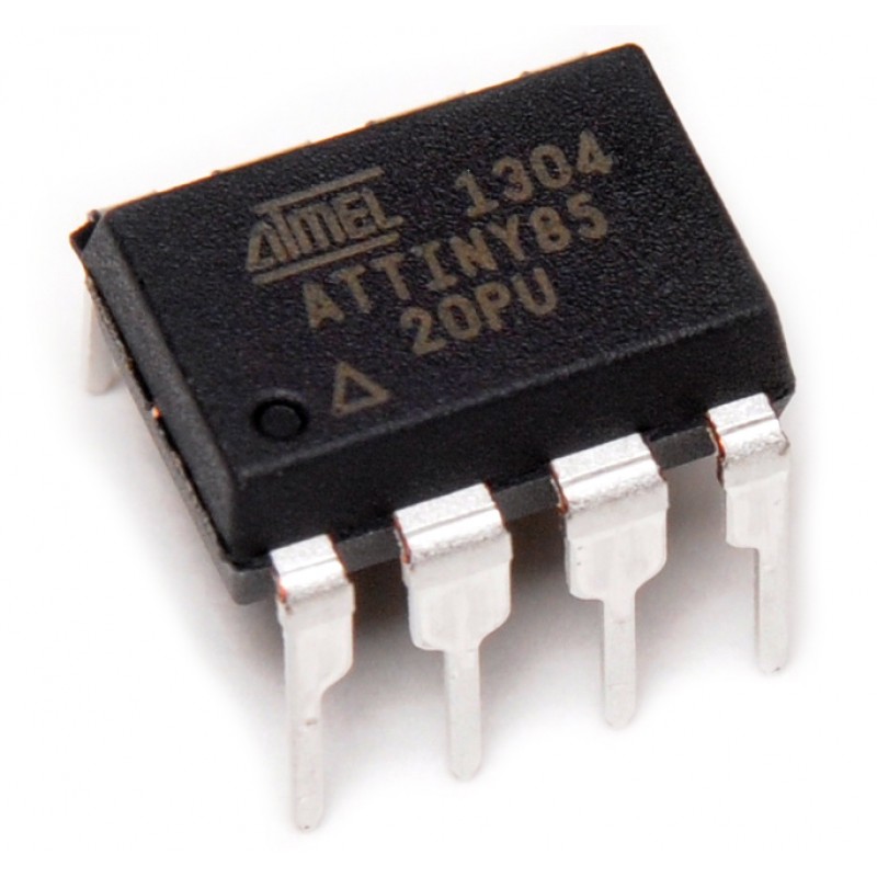
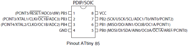
For information about ATtiny IC you can read about it on RS. I’ve included the pinout information as well as an image of the chip https://www.rs-online.com/designspark/basics-of-attiny85 . This is a great chip for deadbugging. It has a good size so the pins can be easily soldered. But it is also easy to program.
pin information for ATtiny
- Pin 1: analogue pin ADC0 and is used for analogue sensors
- Pin 2: is analogue pin ADC3, also for crystal oscillator XTAL1
- Pin 3: analogue pin ADC2 and used for crystal oscillator XTAL2
- Pin 4: should be connected to GND
- Pin 5: used as MOSI for SPI communication, and SDA for I2C communication
- Pin 6: used as MISO for SPI communication
- Pin 7: used as SCK for SPI communication and SCL for I2C communication
- Pin 8: the Vcc Pin 5V
next Step: Programming
There is a comprehensive guide online
https://www.electronics-lab.com/project/how-to-program-attiny13attiny13a-using-arduino-ide/ that demonstrates step-by-step how to program your ATTiny. First, program the bootloader onto the chip so you can then program it as you would for an Arduino board.
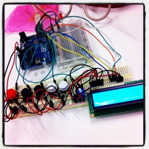
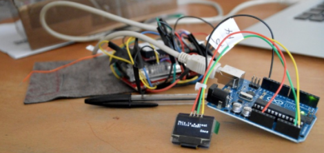
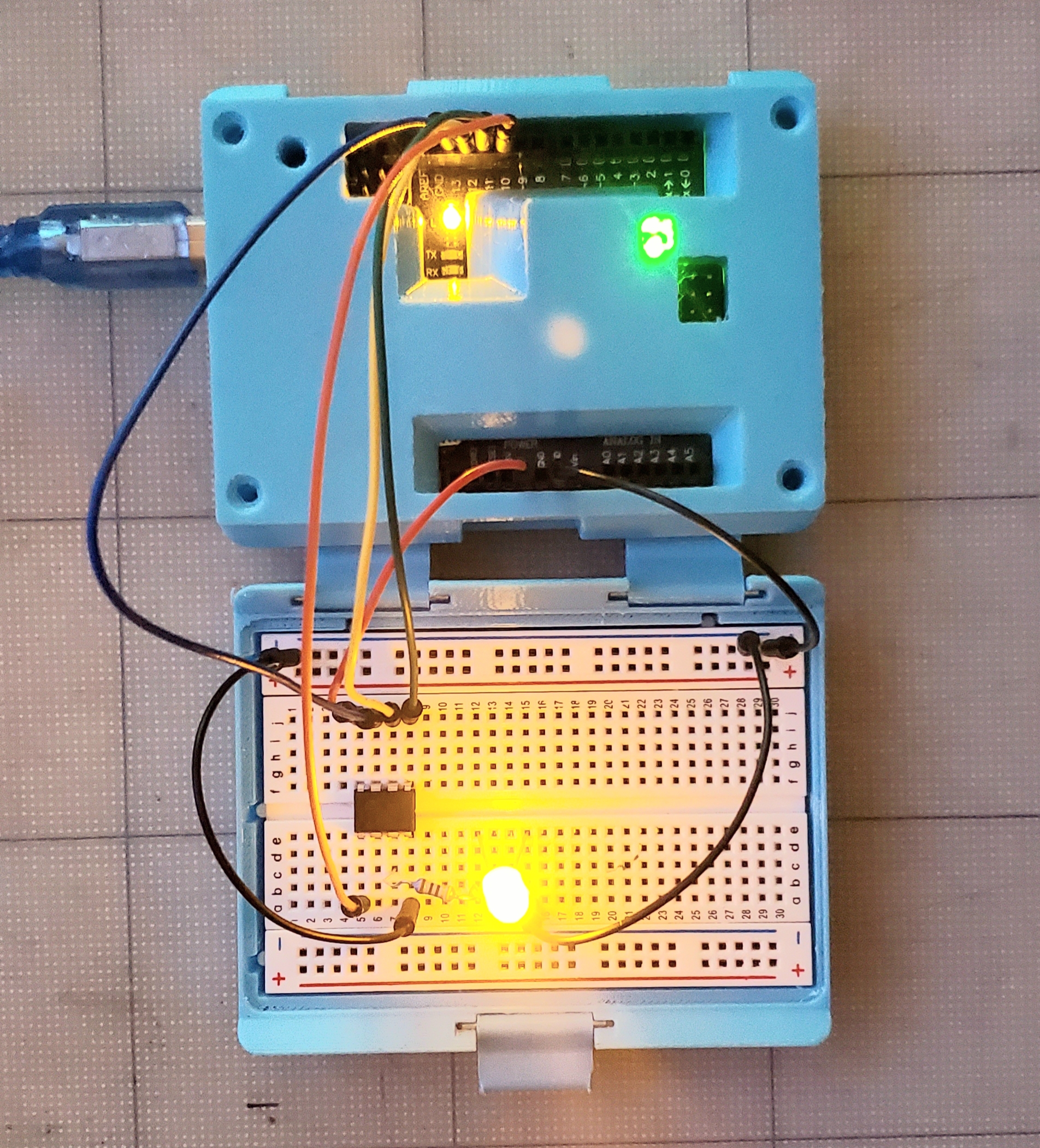
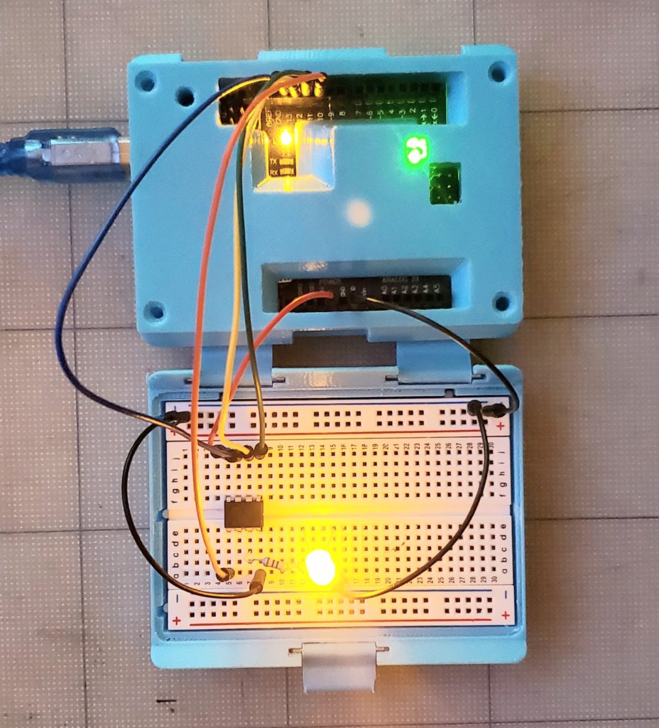
connecting the ATtiny to your Arduino Uno
Connect Arduino 5V to ATtiny Pin 8. Also, connect GND to Pin 4, Pin 13 to Pin 7, Pin 12 to Pin 6, Pin 11 to Pin 5, and finally Pin 10 to Pin 1.
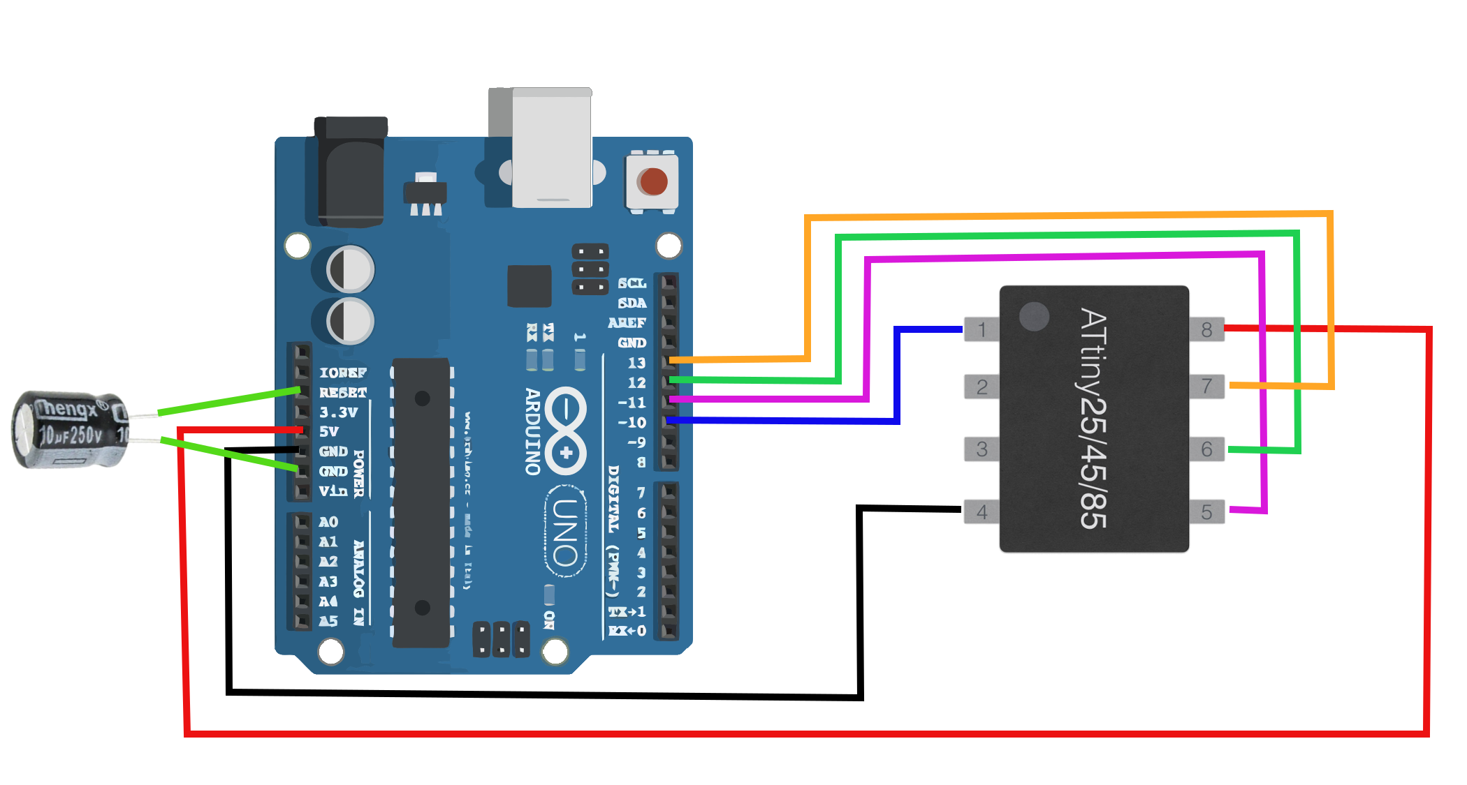
Electrolytic Capacitor (10uF), I didn’t use one.
You should follow the guide on electronics lab but the general steps are after hook up as part of your deadbugging:
- Program ATtiny13: set Arduino as a programmer. This happens by uploading ArduinoISP sketch to Arduino following this path (Files -> Examples -> ArduinoISP) in the IDE.
- Install core files needed:
To install these files, open your Arduino IDE and navigate to the files drop-down menu, then select preferences. Paste this URL “https://raw.githubusercontent.com/sleemanj/optiboot/master/dists/package_gogo_diy_attiny_index.json” where it says “Additional Boards Manager URLs:”. If you already have a URL here and want to add more, separate the URLs with a comma and a space. - Now, navigate to tools-board and click on Boards Manager…. Now scroll down until you see DIY ATtiny and click the install button.
- In order to start programming ATtiny 13, we must burn Bootloader to it. There are two steps to achieve this: first, go to Tools >Board and select ATtiny13,
Note: Pay attention to your ATtiny version, navigate to Tools > Processor Version and select either ATtiny13 or ATtiny25 depending on your chip. (mine is a ATtiny25) - tools > programmer > Arduino as ISP
- and second, click the Burn Bootloader button at the bottom of the tools drop-down menu.
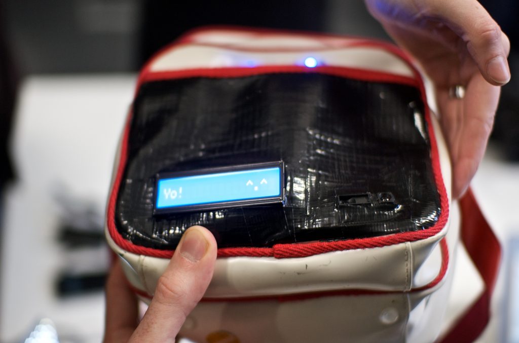
success?
If you see the success message then you are ready to try the ATtiny.
Maybe upload an Arduino IDE example like the Blink sketch.
simple LED Blink sketch
Upload the sketch to the ATtiny13 (using the Uno board and the ‘Arduino as ISP’ programmer and wiring) – then you have a fully-functional Arduino ATtiny13!
int led_pin = 4;

void setup() {
pinMode(led_pin,OUTPUT);
}

void loop(){
digitalWrite(led_pin,HIGH);
delay(1000);
digitalWrite(led_pin,LOW);
delay(1000);
}
modified code for flicker LED effect
Once you have been able to load up the blink code successfully, you can upload the flickering LEDs code that has been provided in the original post at Tinker Log. There was only a tiny modification to get it to work in Arduino.
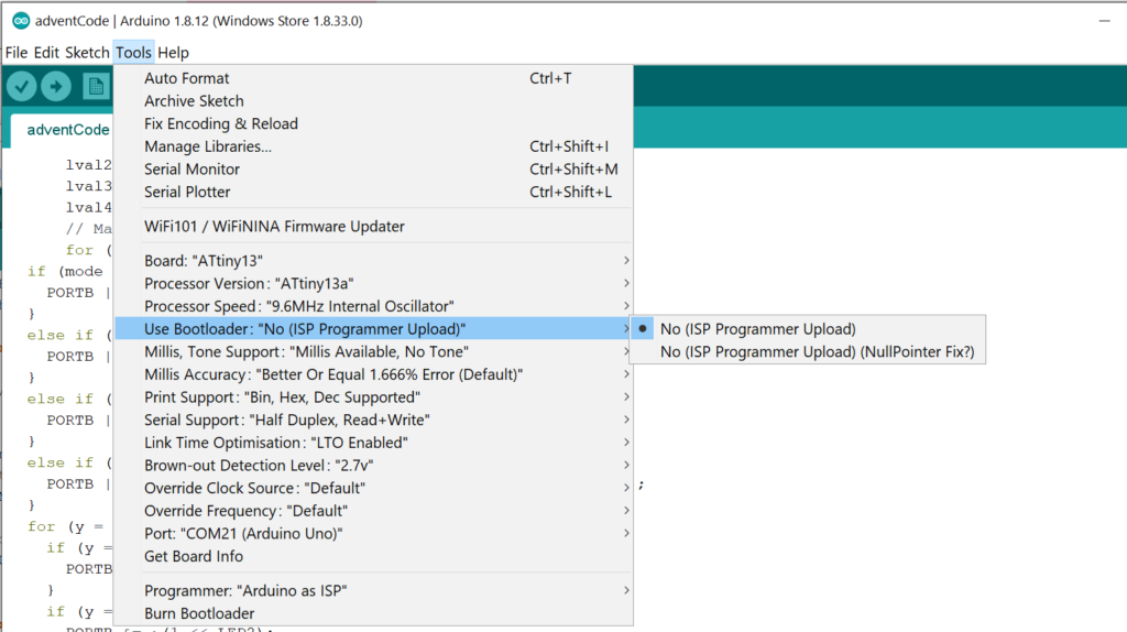
Choose the correct board and board settings. Below are some of the settings I’ve used.
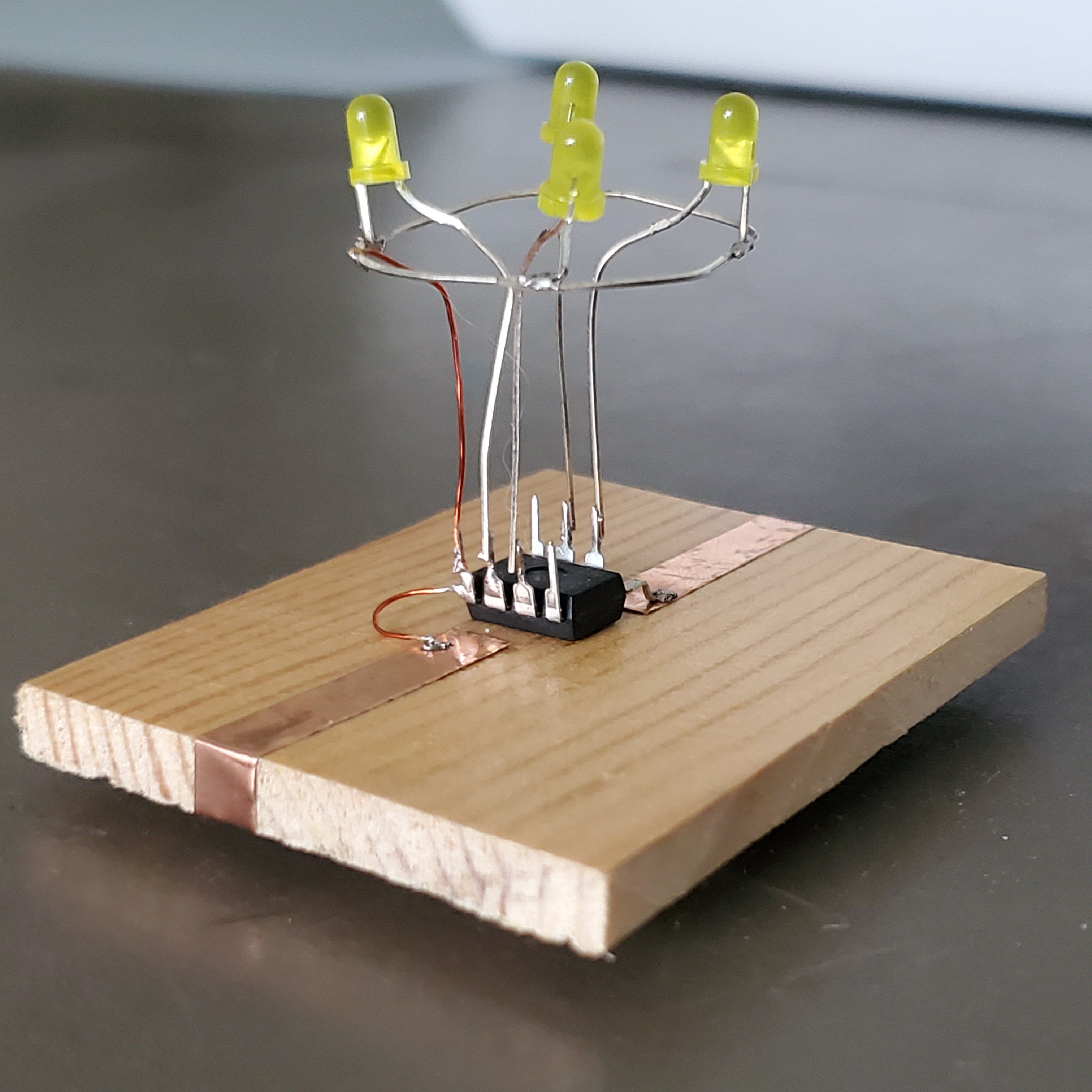
soldering the Circuit
- All cathodes of the LEDs are connected to form the ring.
This is an intricate part of deadbugging. I first took 4 LEDs to sacrifice and practice bending the ground leg of them into this circle form. I then tried a few different ways to solder them together. In the end, I put the anode (positive) leg into a mini breadboard to hold them once they were already bent into shape. Then I used a crocodile clip to hold the leg together in place as I soldered it.
- The anodes are bent inwards to be soldered to pin 2, 3, 6 and 7 of the ATtiny13.
- Use wire to connect the common cathode (soldered) to the GND pin.
- The GND pin is then connected to GND of the battery.
References
Dietz, P.H., Yerazunis, W.S., Leigh, D.L., “Very Low-Cost Sensing and Communication Using Bidirectional LEDs”, ACM International Conference on Ubiquitous Computing (UbiComp), October 2003. PDF Download
Tutorial Online on Tinker Log [Accessed April 20, 2020].
Comprehensive guide online to programming an ATtiny Online Available:
https://www.electronics-lab.com/project/how-to-program-attiny13attiny13a-using-arduino-ide/ [Accessed April 18, 2020].
Installing additional boards,
https://raw.githubusercontent.com/sleemanj/optiboot/master/dists/package_gogo_diy_attiny_index.json to add the ATtiny to Arduino Available Online [Accessed April 15, 2020].
Circuit diagram online available from Maker Portal [Accessed April 18, 2020].
Another version of the circuit via Sprite Sprite’s minimalistic version Available online [Accessed April 20, 2020].
Extra
Have you made an aircircuit or done deadbugging before? Do you have any small projects? What skills have you been working on? Drop me a comment!