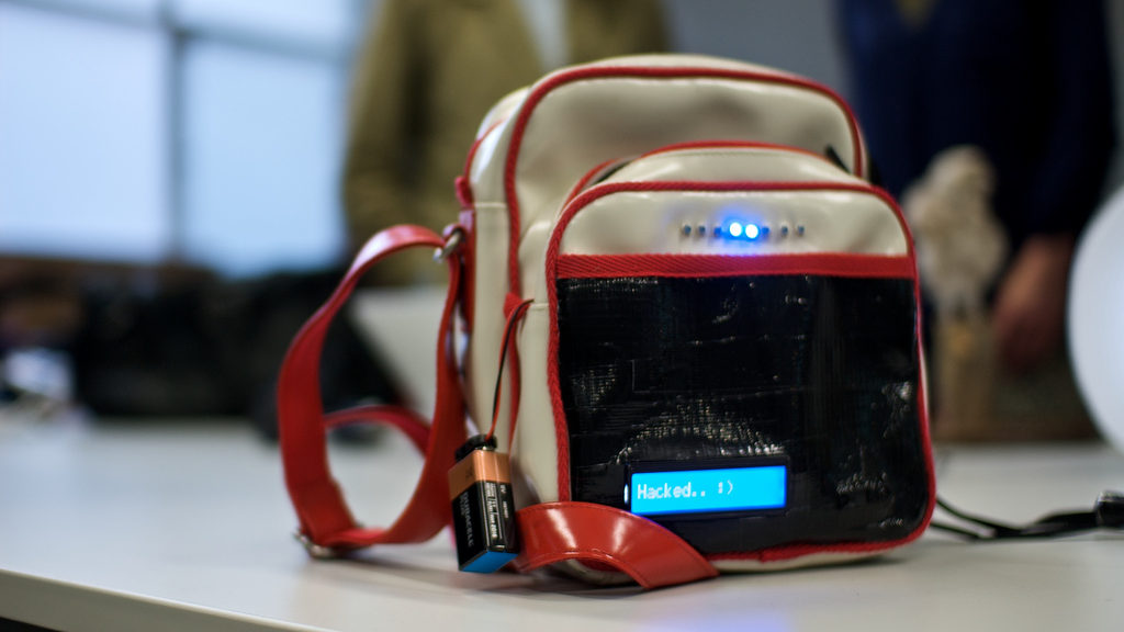

This prototype (Message Bag 1.1) builds on the initial message bag, and has the basic features of it enhanced. It serves as an initial testing prototype to work through initial flaws and design decisions as well as features and how they would work, or what purpose they would serve. The initial message bag that was created has had the components removed and they are built from the ground up, being modified or altered to better and more accurately serve the needs of this prototype.
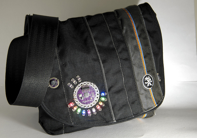
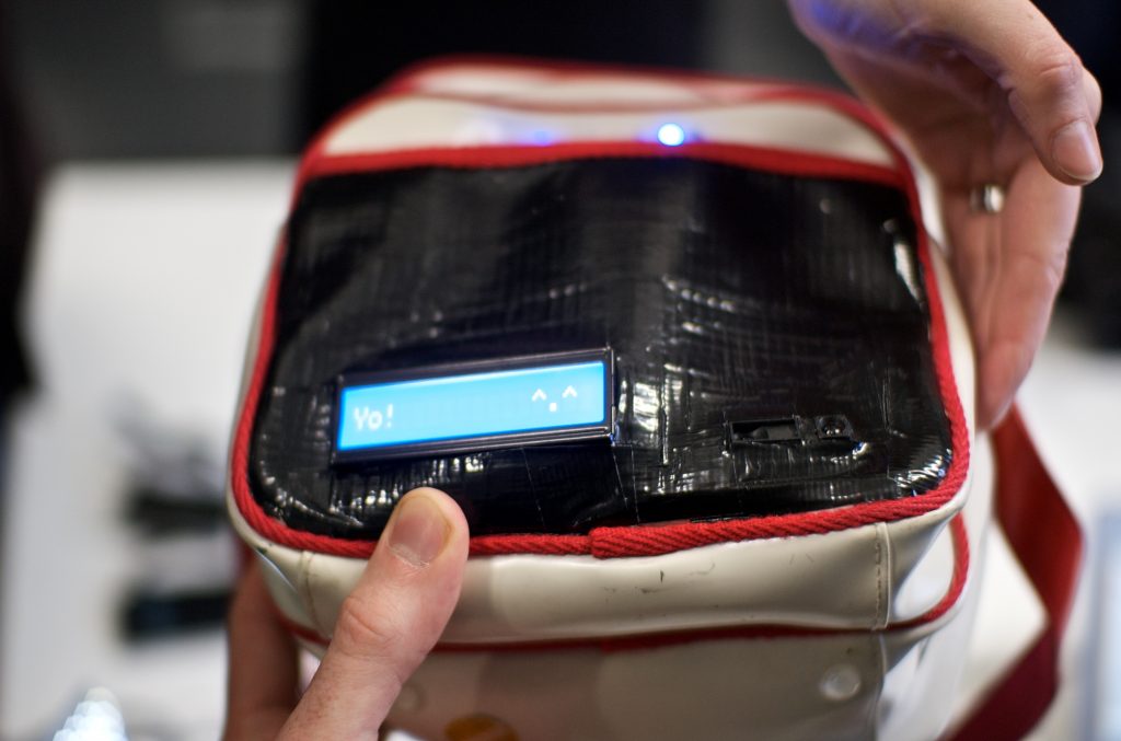
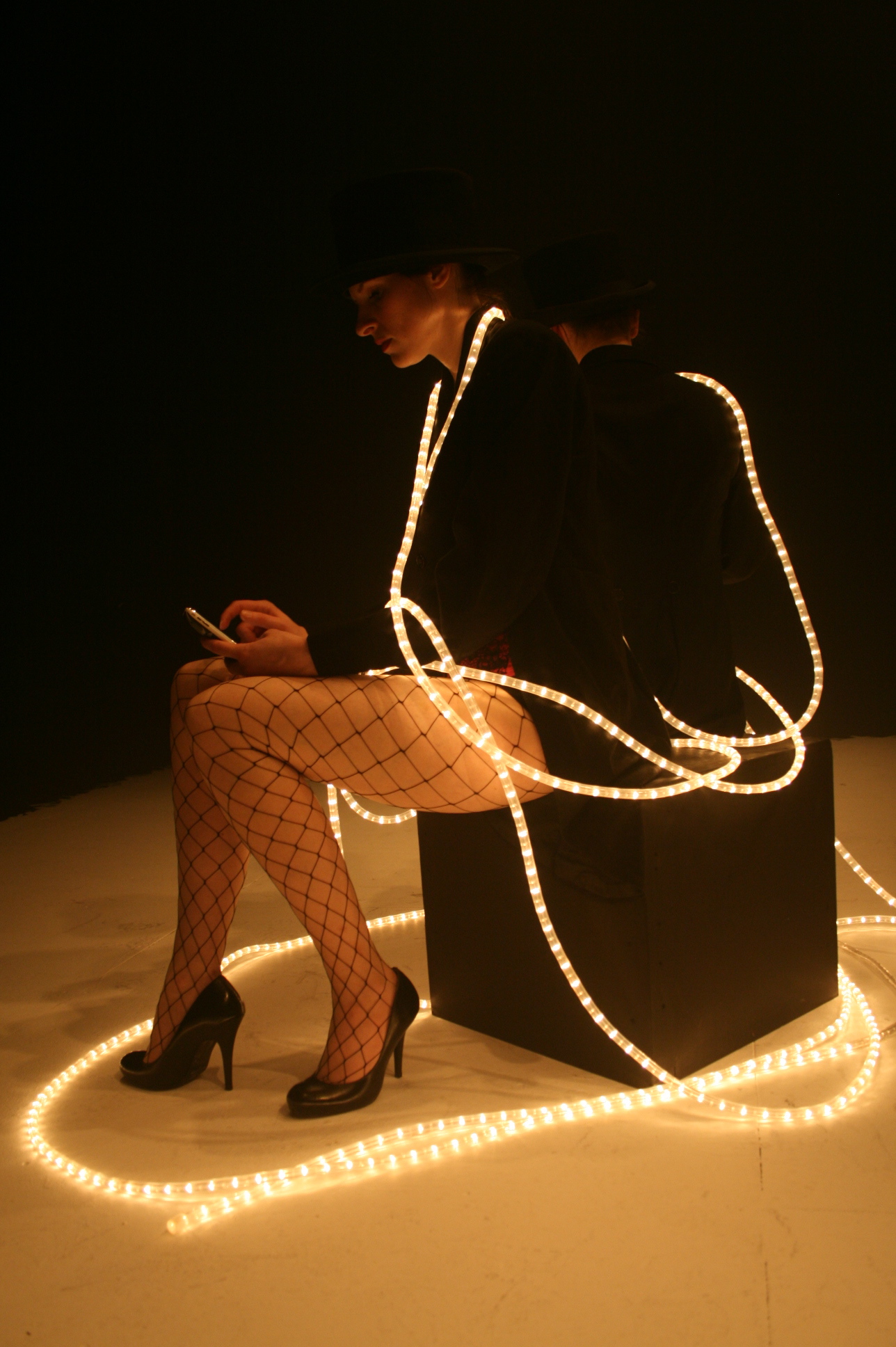
Message Bag, Nov. 2011
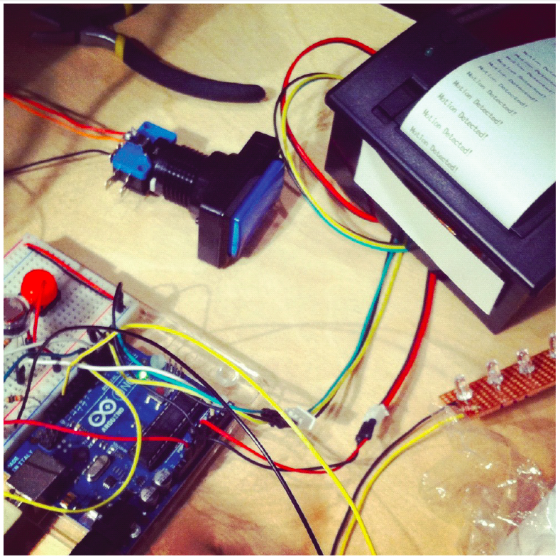
Message Bag has an integrated LCD for messages as well as an RFID that activates LEDs so you know what items you have packed. Using Arduino.
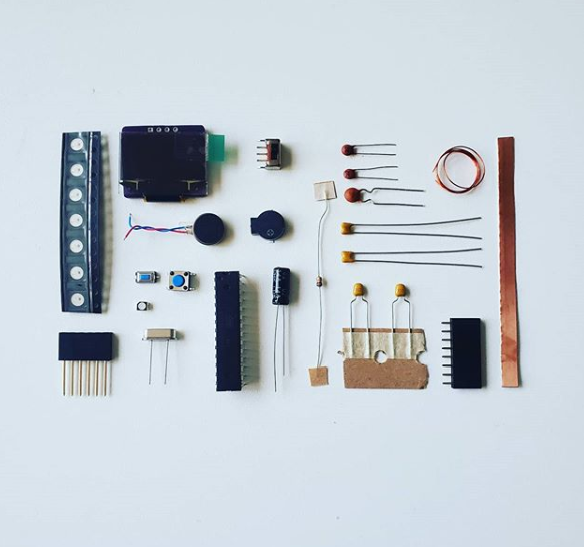
Component list
for V1.1, these components are available from most sites that sell Arduino items
Ingredients:
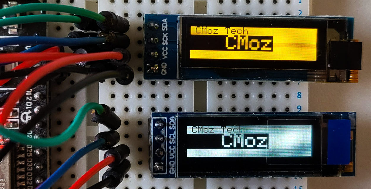
- LCD 16 x 1 Screen Blue Negative Mode, White Led Backlight
- Sharp Distance Measuring Sensor This would be used to display messages based on the distance of people to the bag
- RFID Reader and the RFID Reader breakout
- ID12 Breakout
- Photo Resistor Light Sensor
- Piezo
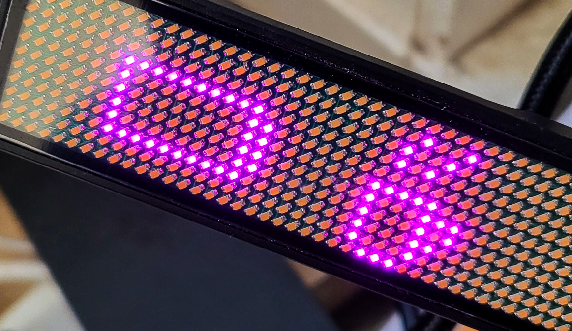
- Pink LEDs
- Teensy
- assorted wires and other similar components
Component Use
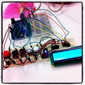
Method for Arduino Board 1 LCD Display:
LCD
Initial thoughts were to get an LCD screen to display messages, so I did some research into how they worked, what different kinds there were, this information from Arduino was very close to what I was looking for. My LCD had a back light so there were 2 more wires to add, an additional power and ground to power the screen.
I also incorrectly assumed the 16 x 2 size screen or larger would be too much for a first project so I went with a 16 x 1. This caused me a lot of challenges that I wasn’t aware of at the time. This post from Tronixstuff, had a good rundown of the different types of LCD screens you could use.
The issue with the 16 x 1 display was that it displayed 2 rows of 8 characters side by side. This firstly took me a log time to realise and work into the code as well as it didn’t really have the exact effect I was after. Due to time constraints, I went with the one that I had ordered, I would like to replace this or do a different screen if I make another similar item. I would go for 16 x 2 as a minimum.
You must include the LiquidCrystal library, and here was the code for that as well as setting the pins.
You must then add to void setup() the initialization of the LCD by telling it the number of rows and columns.
lcd.begin(8,2); // start the LCD, a 16 x 1 has 2 rows of 8
Then within loop() where you want your display to print something you need the following code, so mine was within sensor values and if statements dependant on the values of the sensor readings:
lcd.print("You are too far.");
Distance Sensor
The distance sensor was one of the first sensors I implemented to test it and get the code working initially to get readings.
The idea here was that it would change messages based on the distance of the bag to people. The issues with this is it didn’t track huge distances, and also it could literally detect anything so it wouldn’t be changing according to people, so it was pretty inaccurate for my purpose. Other issues became that it was reading values pretty quickly, even with a slight delay, so the messages were recycling too quickly. When I slowed it down, it seemed to users that the change wasn’t registered. After watching people use it and getting feedback this would be something that I would need to alter.
Photo Resister
This sensor was pretty straight forward although I had noticed I was getting erratic readings when testing it – so I swapped the resistor and it seems that the one I had been using was broken. Switching the resistor fixed it and it worked well as a way to light the bag in the dark. A future addition would be to be able to turn off these lights if the wearer didn’t want them on. Code from Arduino is pretty straightforward as well as the schematic.
Method for Arduino (Teensy) Board 2 RFID Reader :
RFID Reader
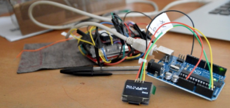
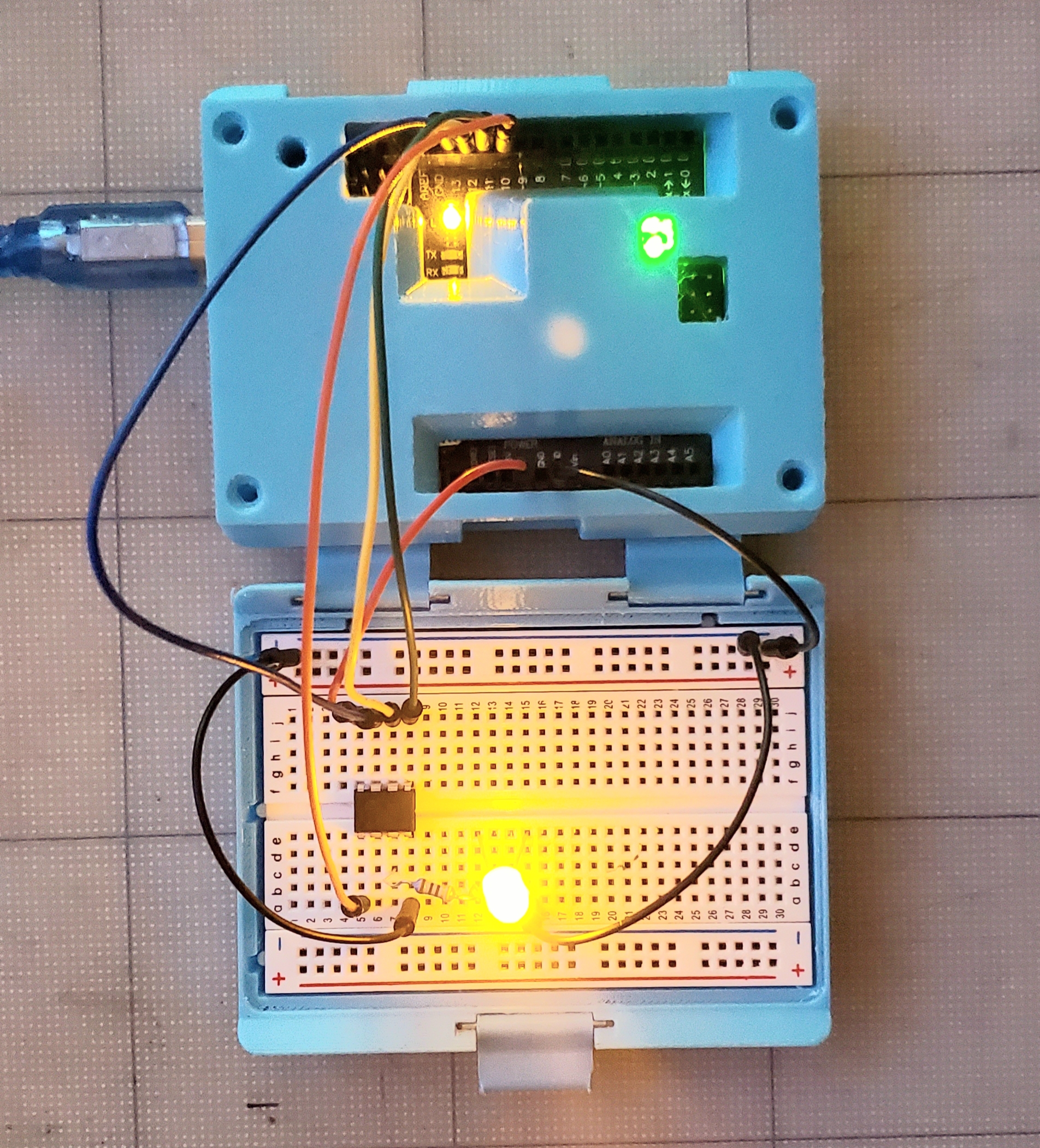
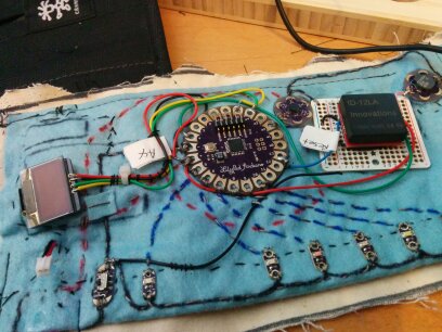
The RFID code was on a separate board and part of the bag, so essentially I had two separate code files, one for each Arduino. The reader I was putting on a breadboard with a Teensy so that the whole unit could fit into the inside pocket of the bag. The teensy needed a power source as it doesn’t have that as part of the board so I added power from a battery as shown at pjrc.com.
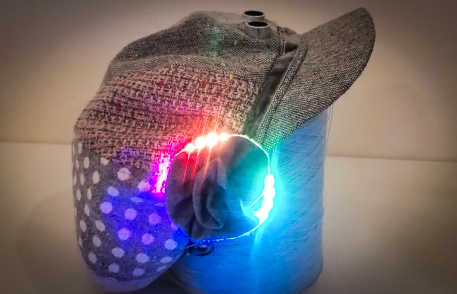
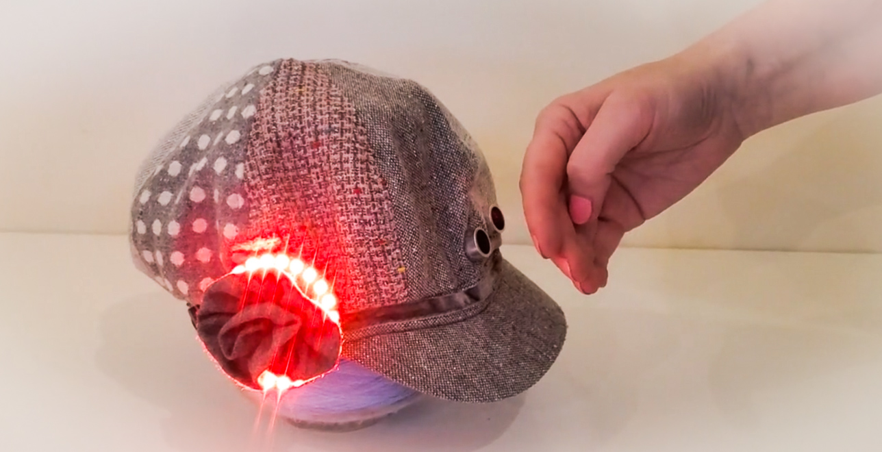
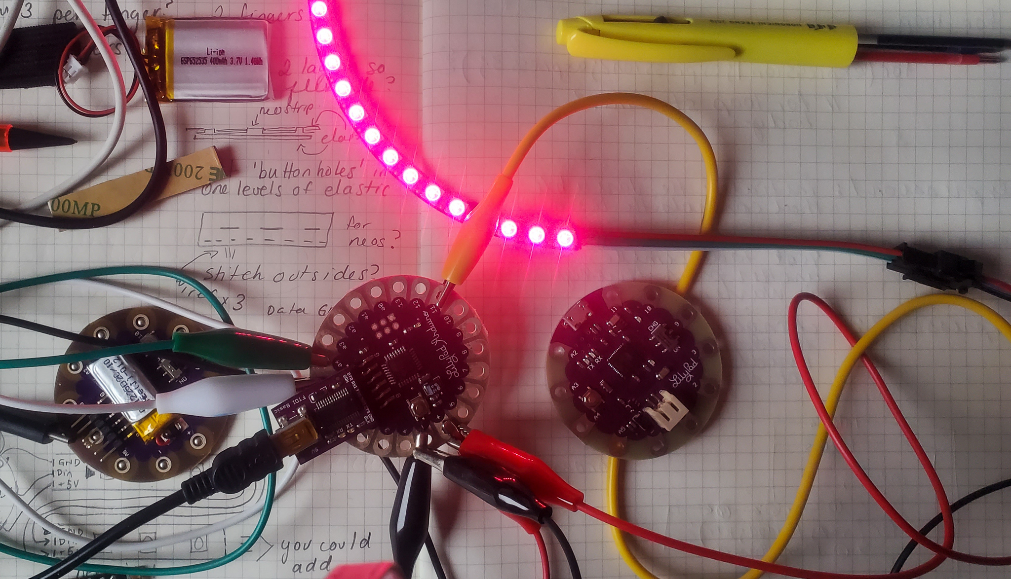
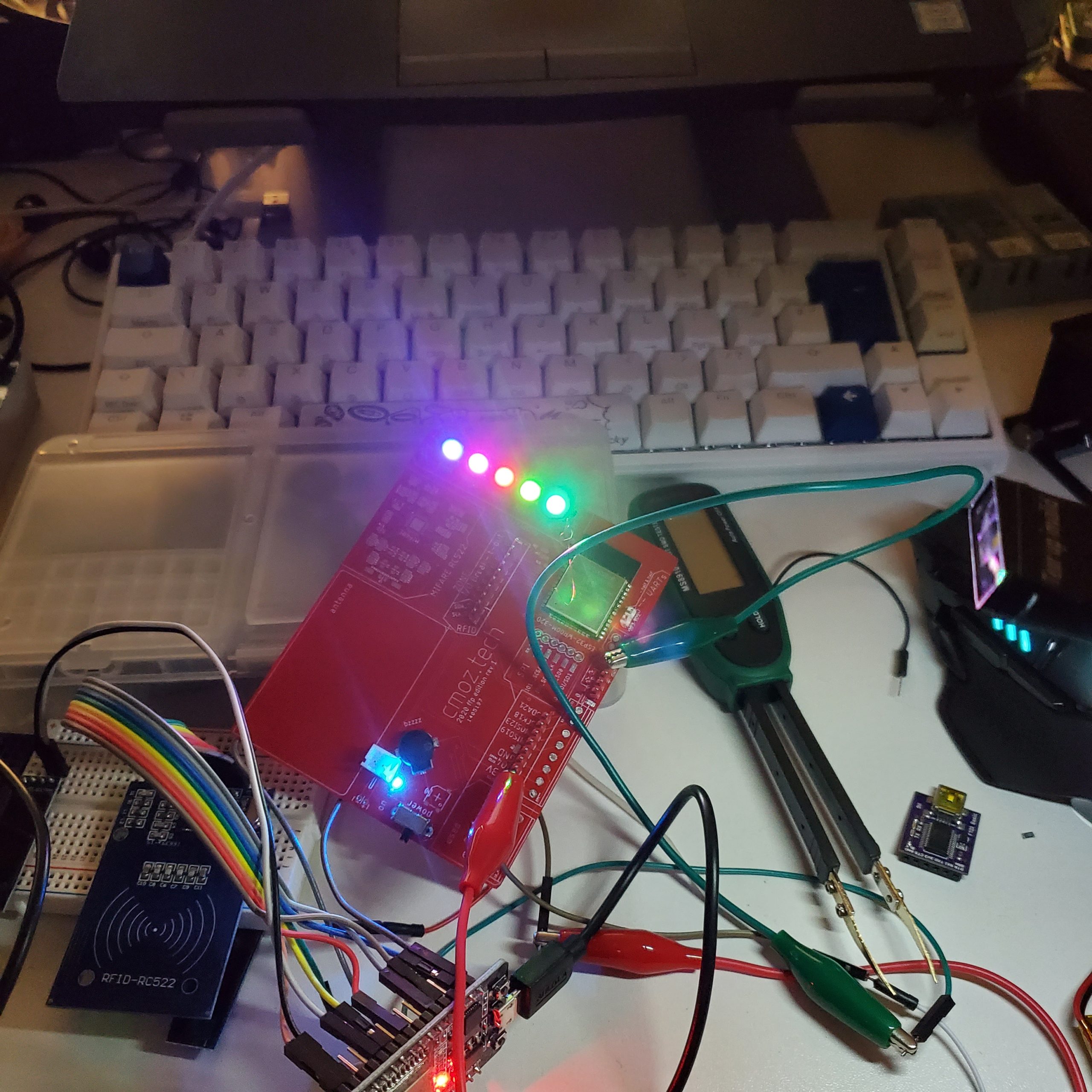
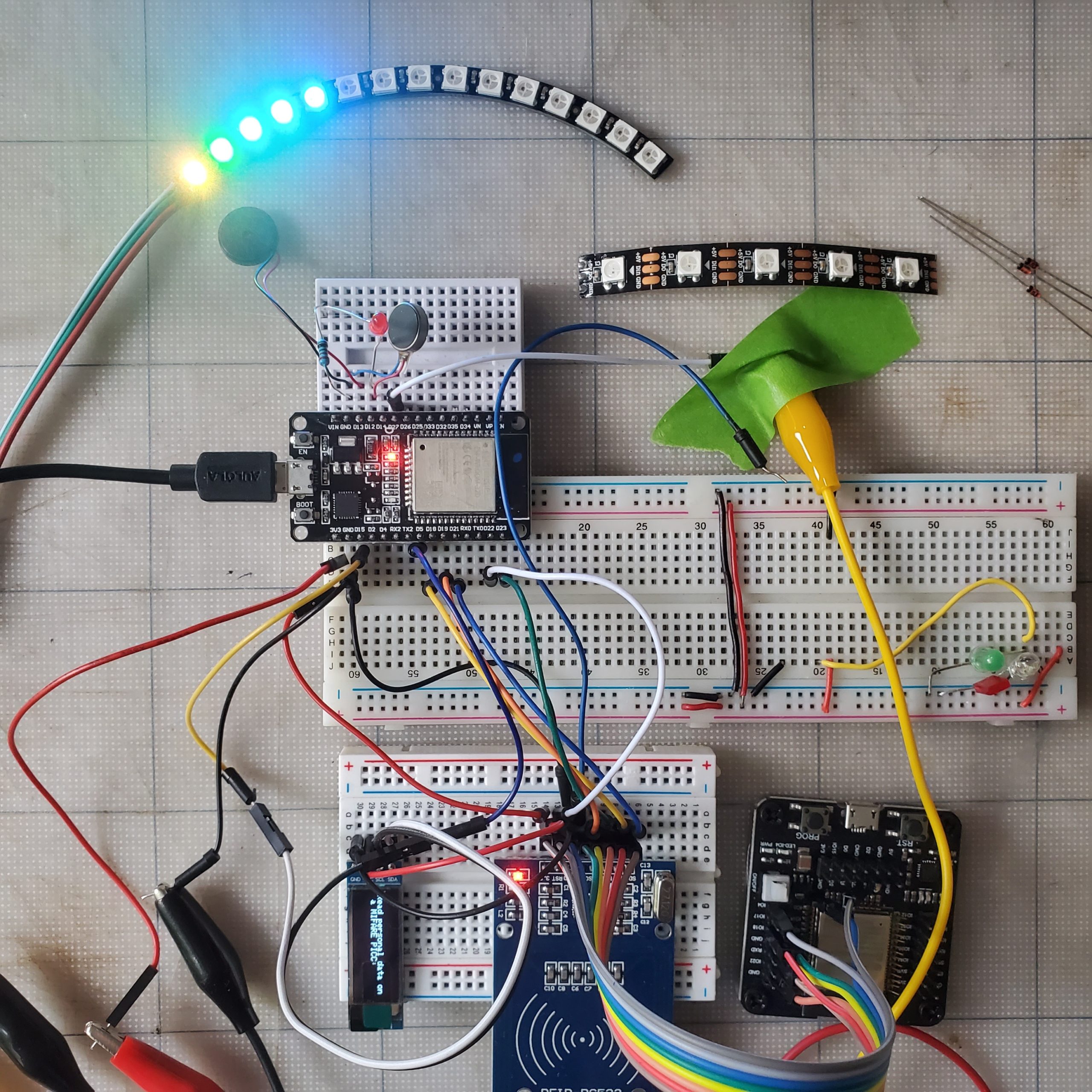
For me the RFID part of the implementation really felt like it was an idea with potential. I loved getting this to finally work and it seemed a good addition to a bag and a feature I would like as well. Here is a short clip showing the LED lighting up when the item is placed in the bag.
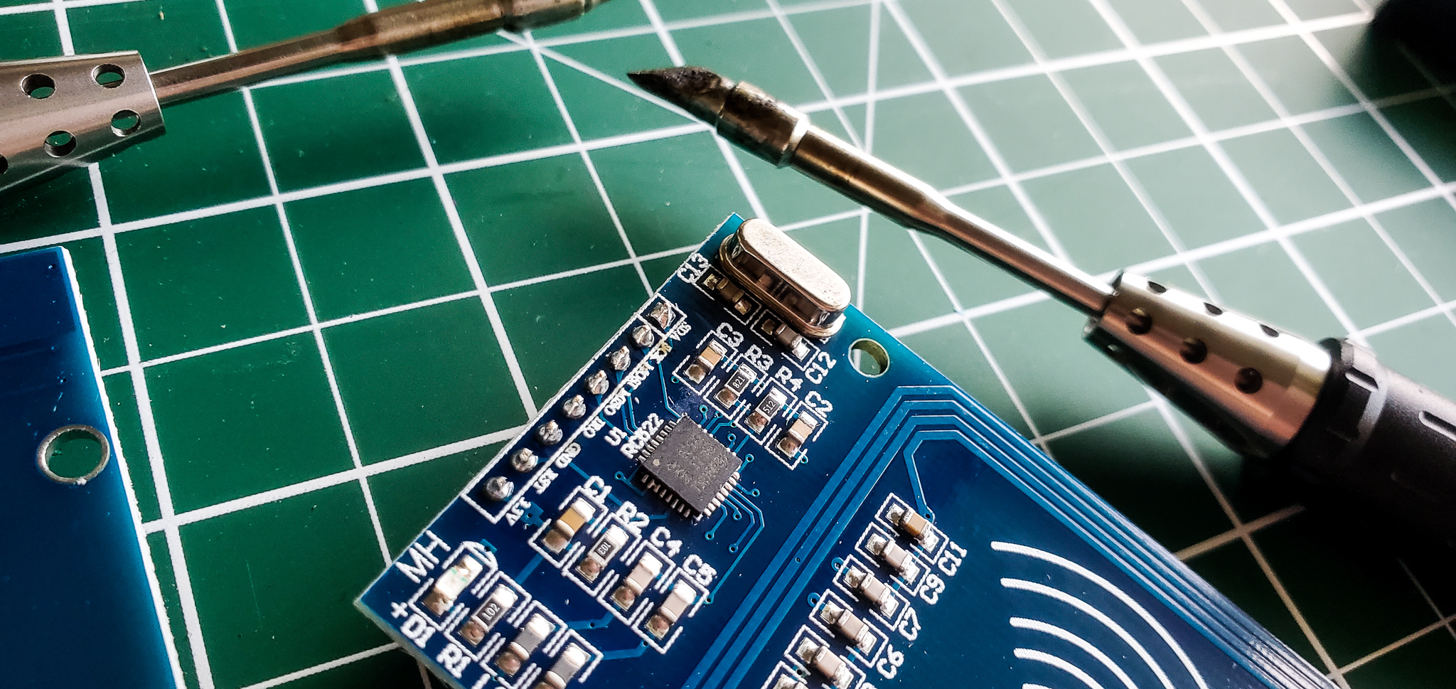
I had an issue with the Reader and it seemed to read the values initially then stopped reading and displaying the values. I tried changing the components, altering the wires, changing the Arduino board and when I was still getting sporadic results, it was suggested that actually my soldering had not made full contact and this could be the issue. I checked the board and it was the problem. Because the board was soldered first into a breakout board it was a really difficult issue to fix so I initially used a screwdriver to bang it closer to make contact with the wire. I have since re-soldered this board and it has fixed the error. As it was my first time soldering I hadn’t realised about this being an issue so although it was very frustrating it was a good lesson to learn. As far as the code goes, initially I put code on to read the tags so I knew which numbers I was reading. Then when the numbers are recognised, some action happens.
In the loop() we are reading the serial numbers. When the code is uploaded you have to remove the wire going to the RX, and then put this wire back so it can send the values we are looking for.
The tags are then checked to see if they match the values we declared already – if not we are given the value on the serial monitor.
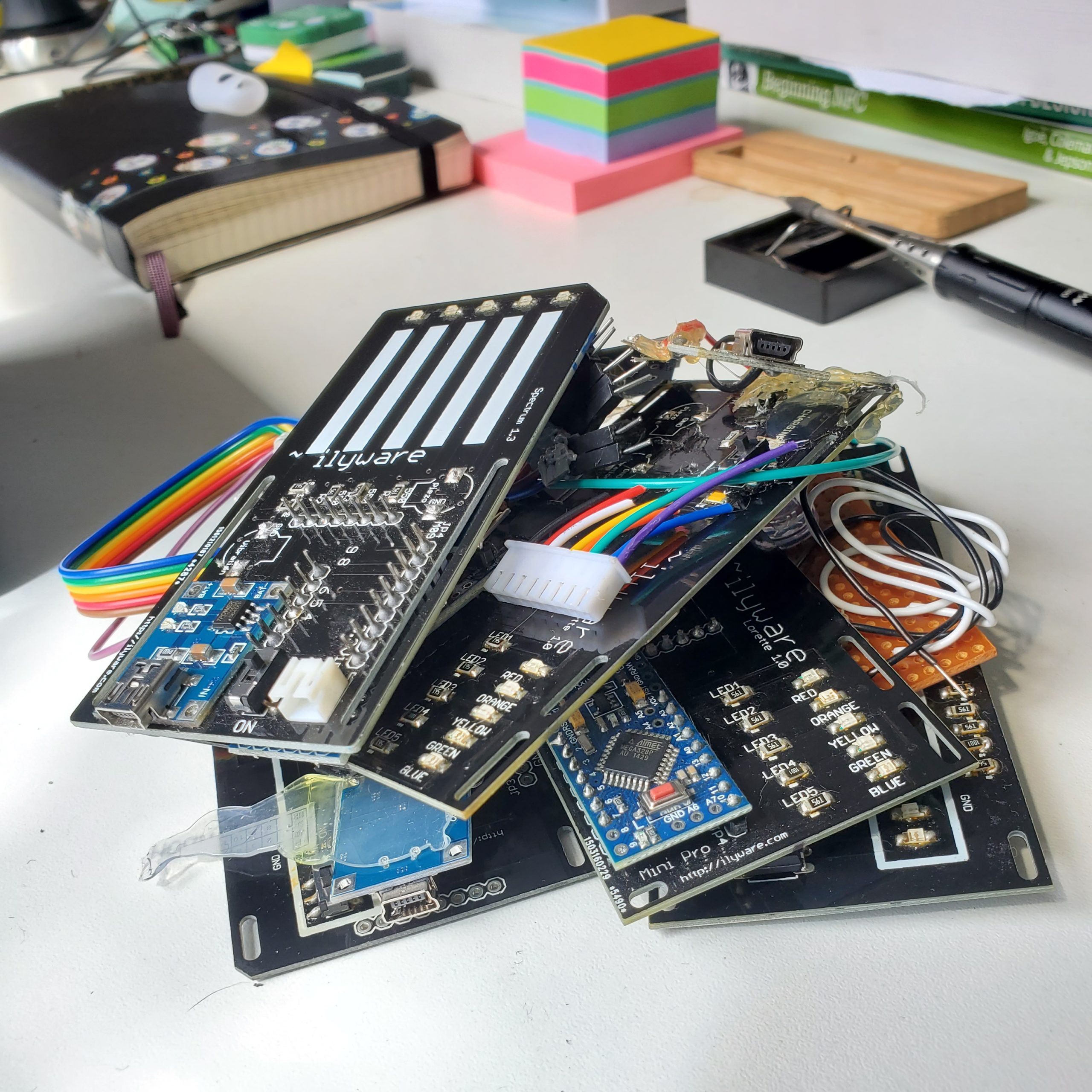
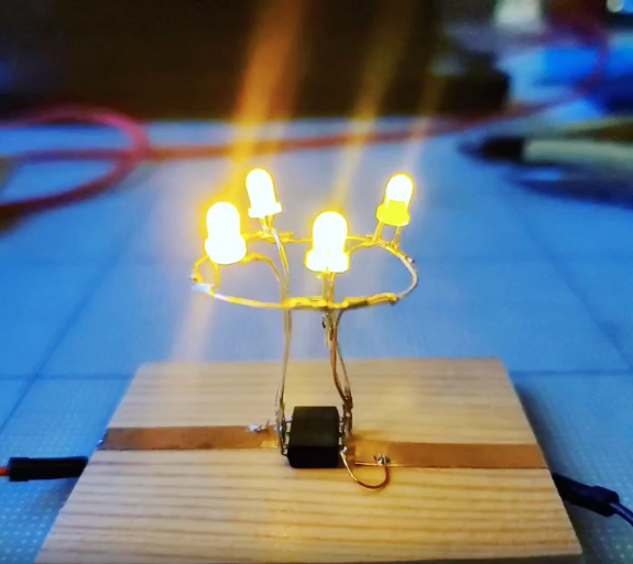
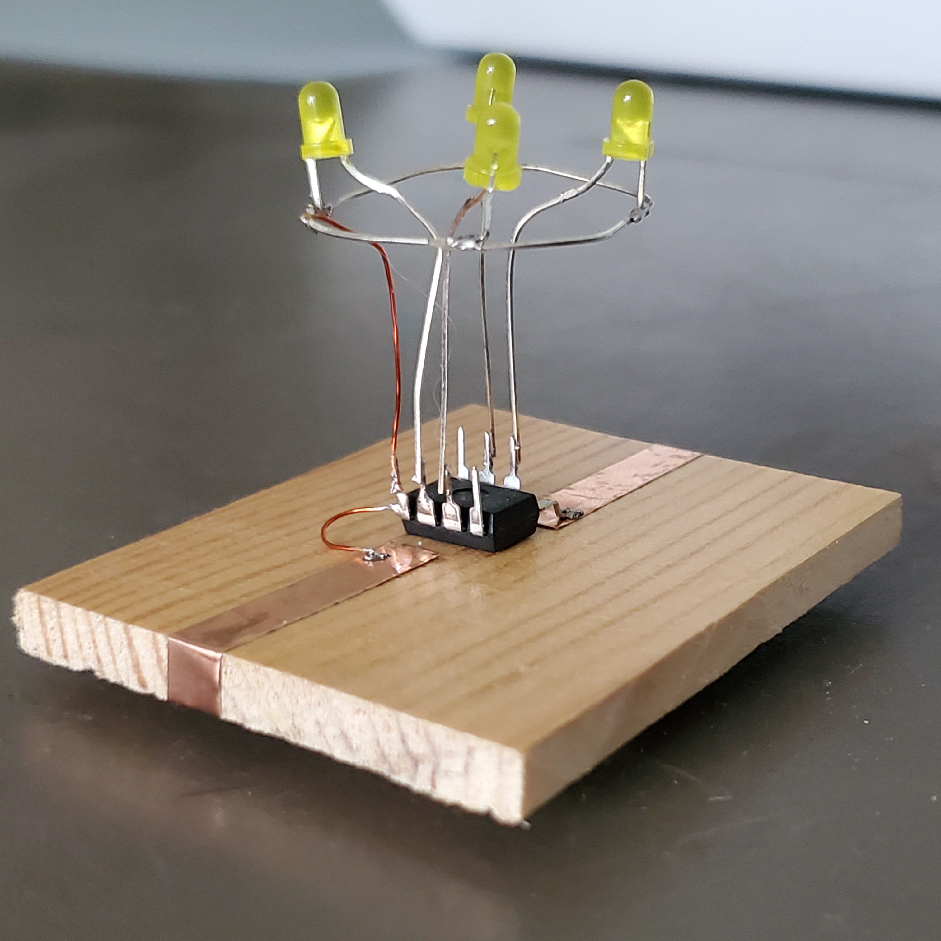
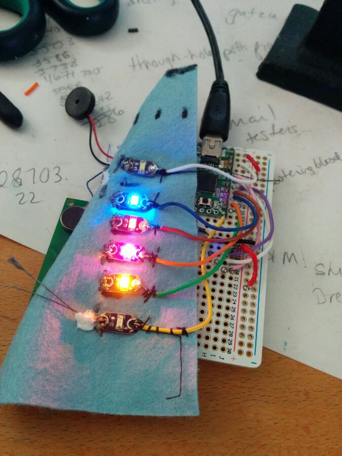
Pink LEDs
This was pretty straight forward to add, I put them on a little circuit board to space them evenly for display on the bag. I had an issue again with my soldering and two of the LEDs were not working. One I had to remove and res-older and the other light was broken so had to be replaced.
Piezo
This was added so that there was feedback for the user when they scan an item. It just emits a noise so they know it was successful. I also included a small LED so they can also see that it was a success in case it’s too loud where they are.
Implementation & Observation

English: Arduino Uno (Photo credit: Wikipedia)
The code I implemented in stages to check what was working and what needed to be tweaked. For this new implementation, I removed the distance sensor from the bag, and in V1 the LEDs responded to lighting in the room, when it was dark they would produce a pattern. In V1.1 this will be a more used feature, and the LEDs will now light to acknowledge that a tag has been scanned, providing visual feedback for the user. In addition to that there is auditory feedback through the piezo – this was implemented in V1, however this time, there is a slight change in that if the tag is recognised, it is a short pulse, slightly higher pitch, when it is not recognised, the tone is a little lower, and lasts for a longer amount of time. With this change in sound, it should make it quicker to notice when an unrecorded tag has passed near the reader.
Additionally, the LCD was used to display messages based on proximity, mostly for a fun factor in the bag for V1, in our second version, we now alter this so that the LCD will display the name of the item that is scanned by the user. Again providing additional cues for them to note what has been scanned.

There are still LEDs to help them to see what is in the bag currently, but this still isn’t done in an ideal way, the LEDs light up on the outside which is helpful, but the tags will have all had to have been pre-scanned and added before hand, so this is something that I would look to modify in a future version. Additionally, just having the items written on the outside is a little clumsy with hand writing on the outside to match the LED, this really needs a rethink.
Additionally, just having the items written on the outside is a little clumsy with hand writing on the outside to match the LED, this really needs a rethink.
Changes
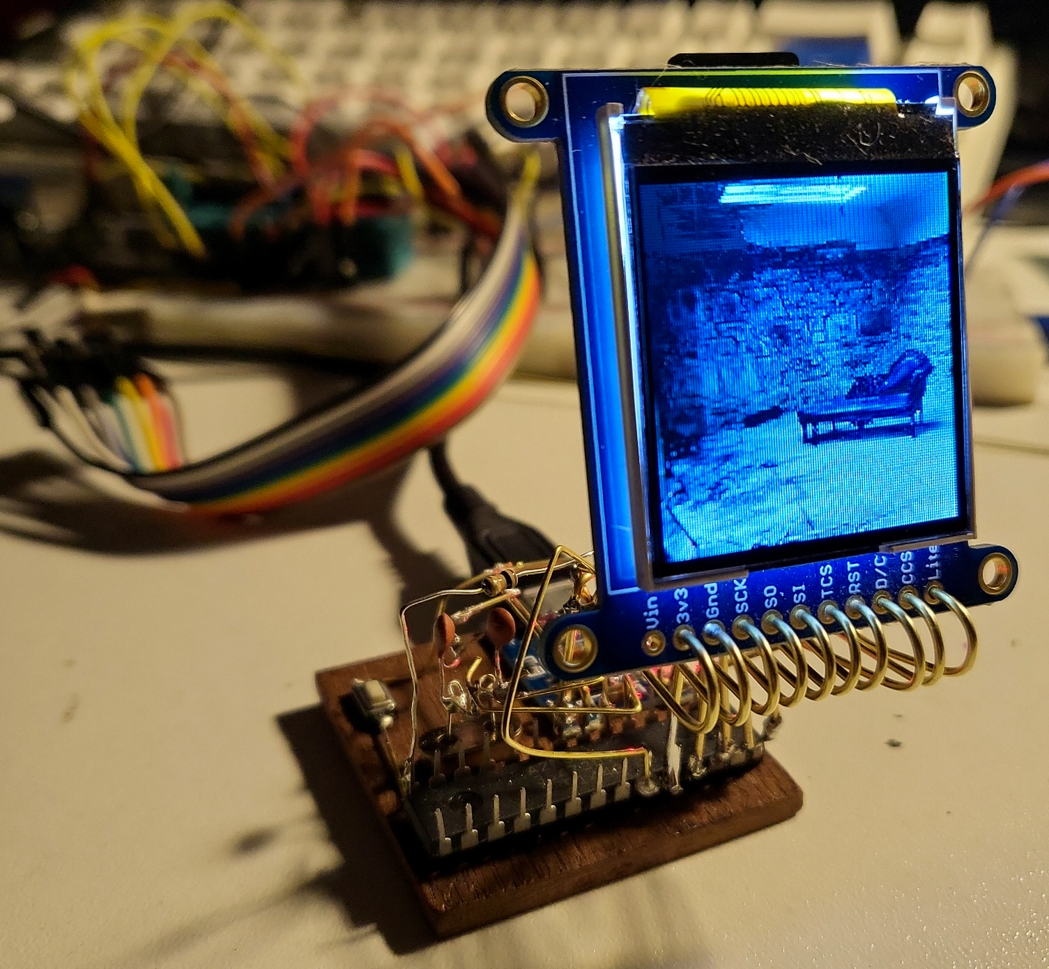
The current RFID reader, the ID12 has limitations in this capacity too. Shown, is the breakout board that needs to be used to mount it a little more easily, by lining up the pins into a breadboard. You don’t need to connect an external antenna which is a really great thing about this particular reader, and there are only a few pins needed. One thing to note is that you will be connecting the RX pin, which is also used when you are uploading your sketches so you must just remove this wire when you upload the sketch, and then replace it for it to work. I have seen an implementation where someone didn’t use this pin and did say it still worked, but it isn’t something I have implemented or tried, and as I will be using a different reader next time it won’t really affect the prototype that will be used for a controlled study.
For a future iteration, I will implement a different reader, that can work more ‘real time’, making note of when an item has been removed from near the sensor, currently this isn’t the case. Also, things like the size of the components will need to be taken into account, and using a teensy in place of the Uno would be another change to implement for message bag 2.0.
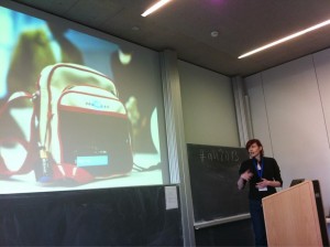
Presented
4th International Augmented Human International Conference in Cooperation with ACM SIGCHI
“focusing on augmenting human capabilities through technology for increased well-being and enjoyable human experience”
Augmented Human 2013 takes place in Stuttgart, Germany, on March 7 and 8, 2013. General Chair is Prof. Albrecht Schmidt.
The link to the short paper being presented MessageBag: Can Assistive Technology Combat Forgetfulness
This is 4th Augmented Human International Conference 2013 and the papers & demos being presented.
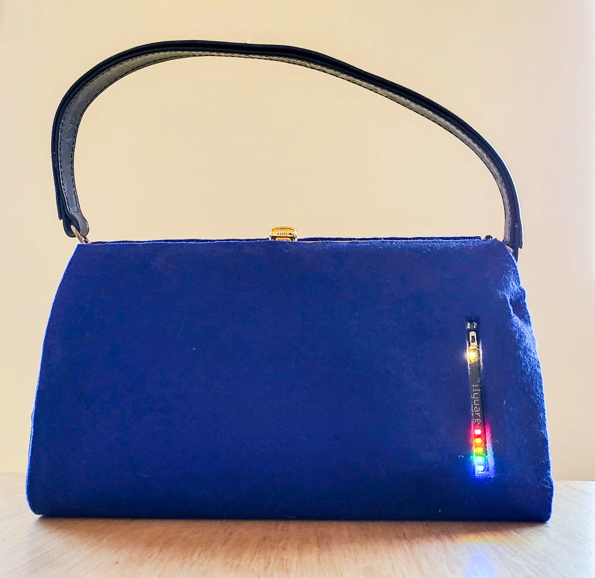
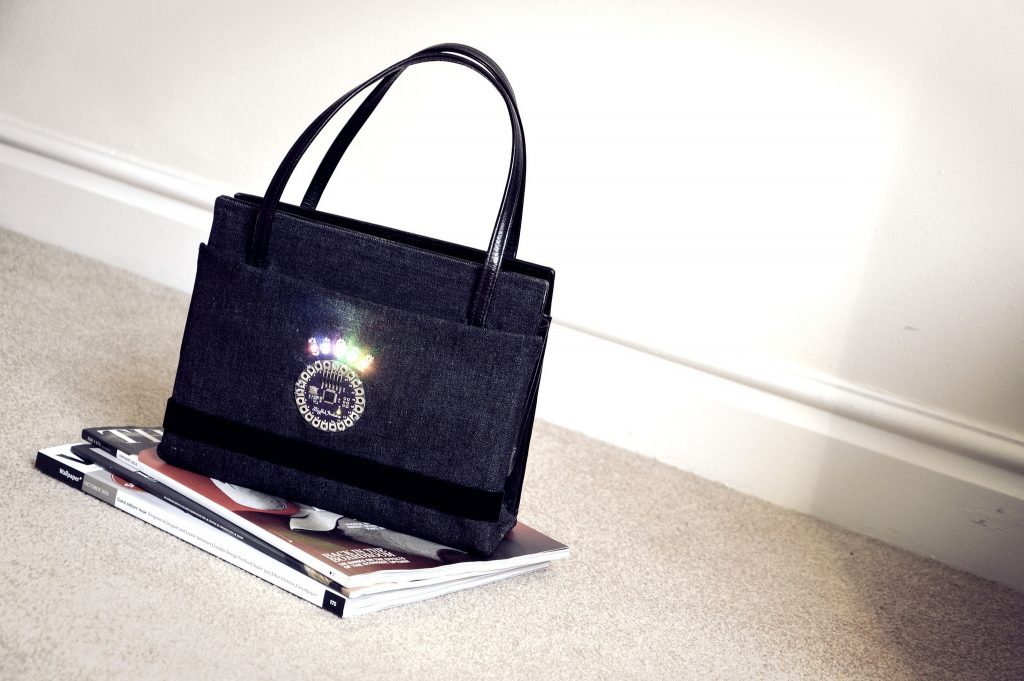
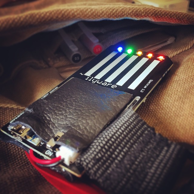
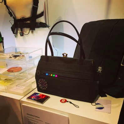
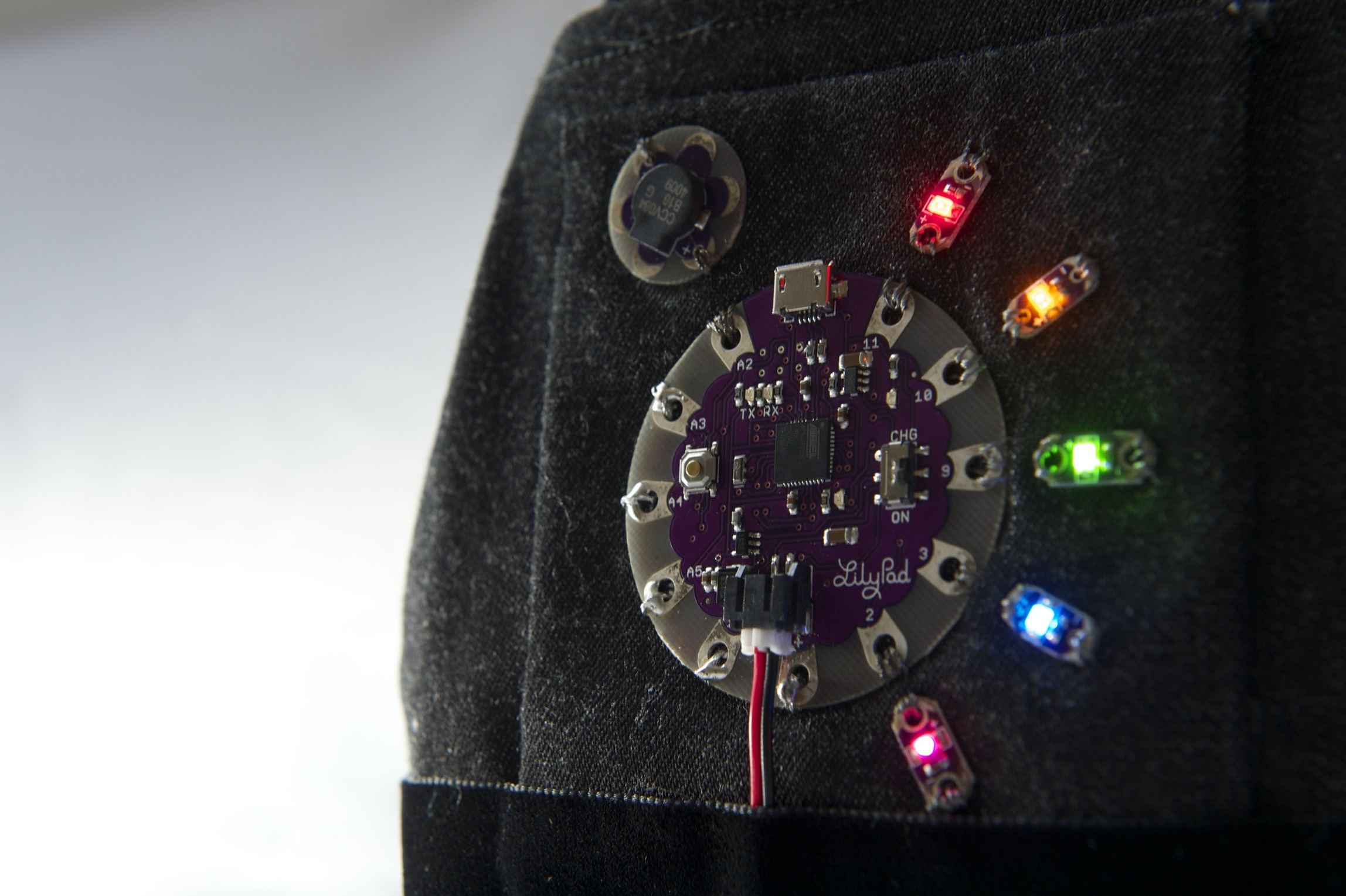
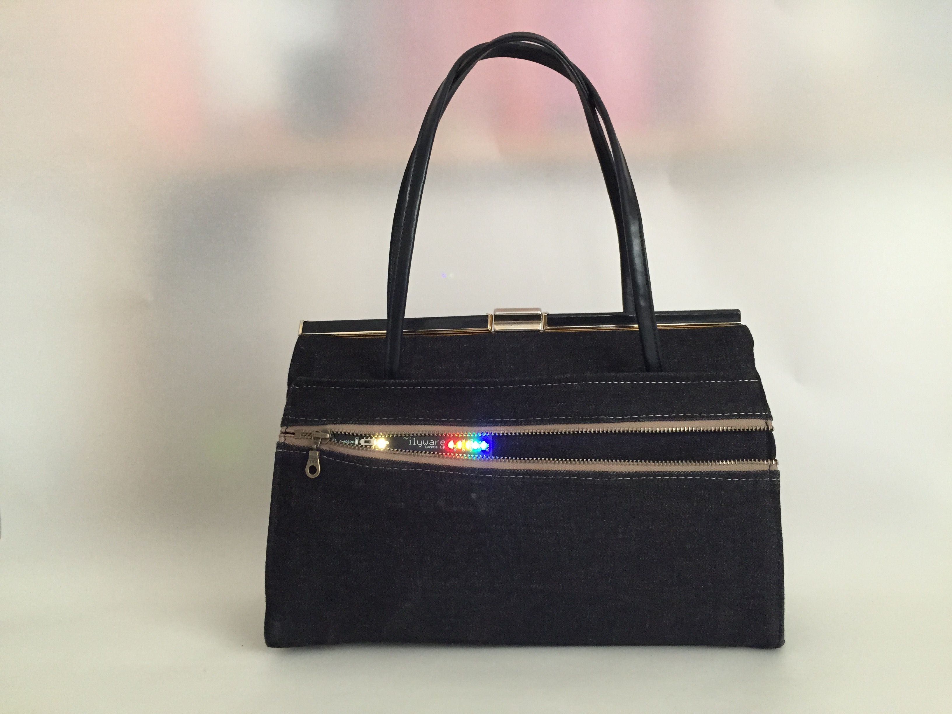
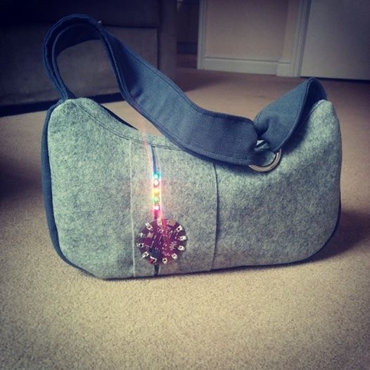
Message Bag v2
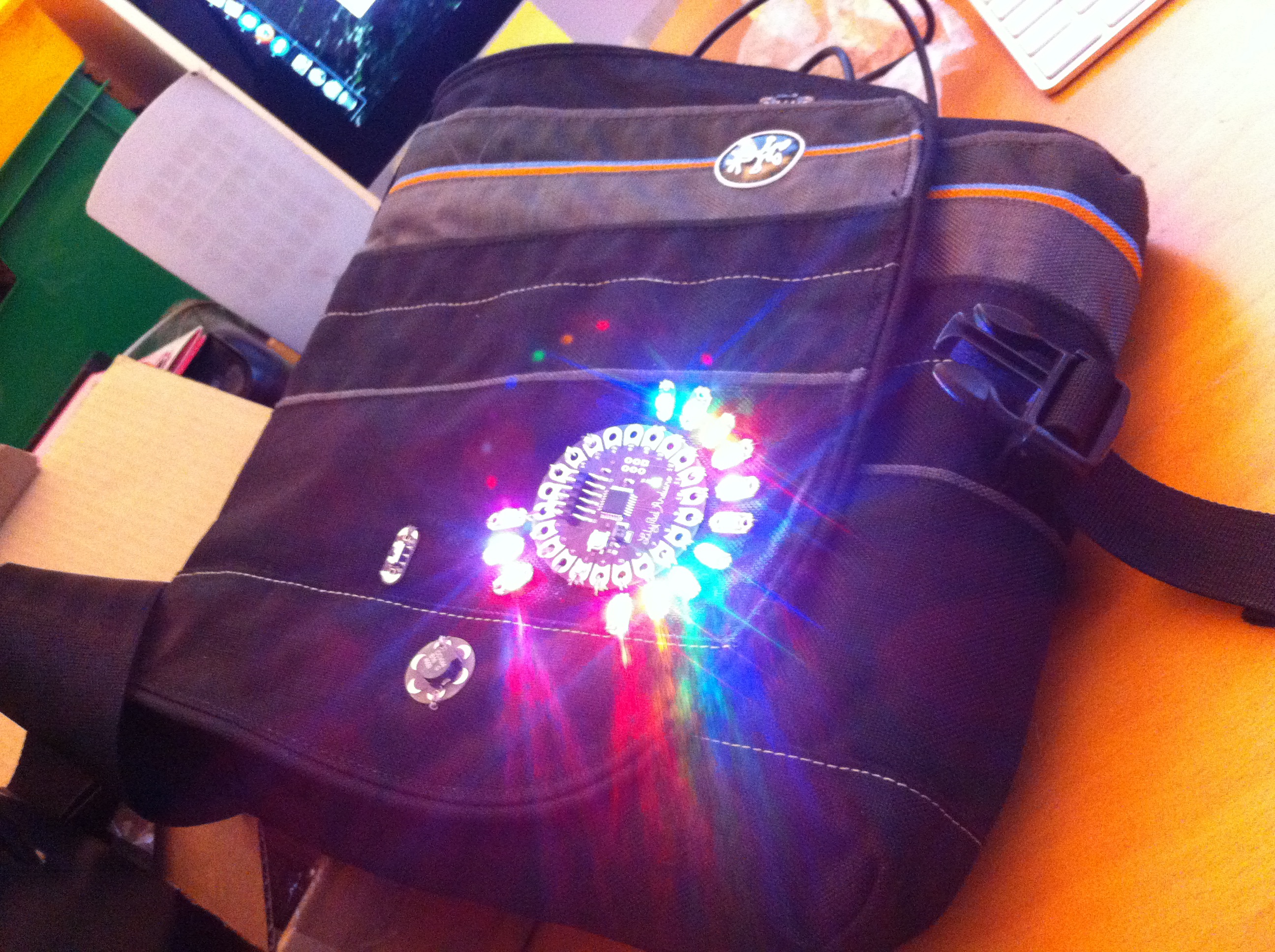
Message Bag v2 created with a Crumpler Bag
This was created after attending the Augmented Human ’13 conference. I wanted to create a second working prototype that was more robust than the first iteration. The first one created was a proof of concept style bag, so that I could visualise how these components could potentially work together, but it also provided valuable insight into how the bag may or may not be used and general problems that will surface when you build a physical object. (note this post does not cover the working description of what it does, it only charts the creation of the bag and observations having used it daily).
There are many challenges when working with wearables, there is a balance with innovative, possibly unusual interfaces, power requirements (which I have been dealing with), possible network resources and privacy concerns. (Starner, 2001) There is also a need to establish what social boundaries there may be which may limit the success of the bag.
ITERATIONS
This second iteration has been built and deployed, it is still a prototype, and I am using on a daily basis. The goal of this is to determine the suitability of the bag and RFID readers for use in our everyday lives, using it every day will bring to my attention things that are not practical, can be improved or just do not work. Some of the issues that were brought up with the first bag are addressed and modified or removed to test what differences there will be within the functionality of the bag. The other main objective of this prototype is to develop a comprehensive understanding of how Message Bag v2 can be used, and use this as a basis for further research into forgetfulness, possible triggers and methods that work best for retrieving a ‘message’ of what you have forgotten and how ubiquitous computing can be further used for alleviating those symptoms of stress associated when an individual does forget.
CHANGES

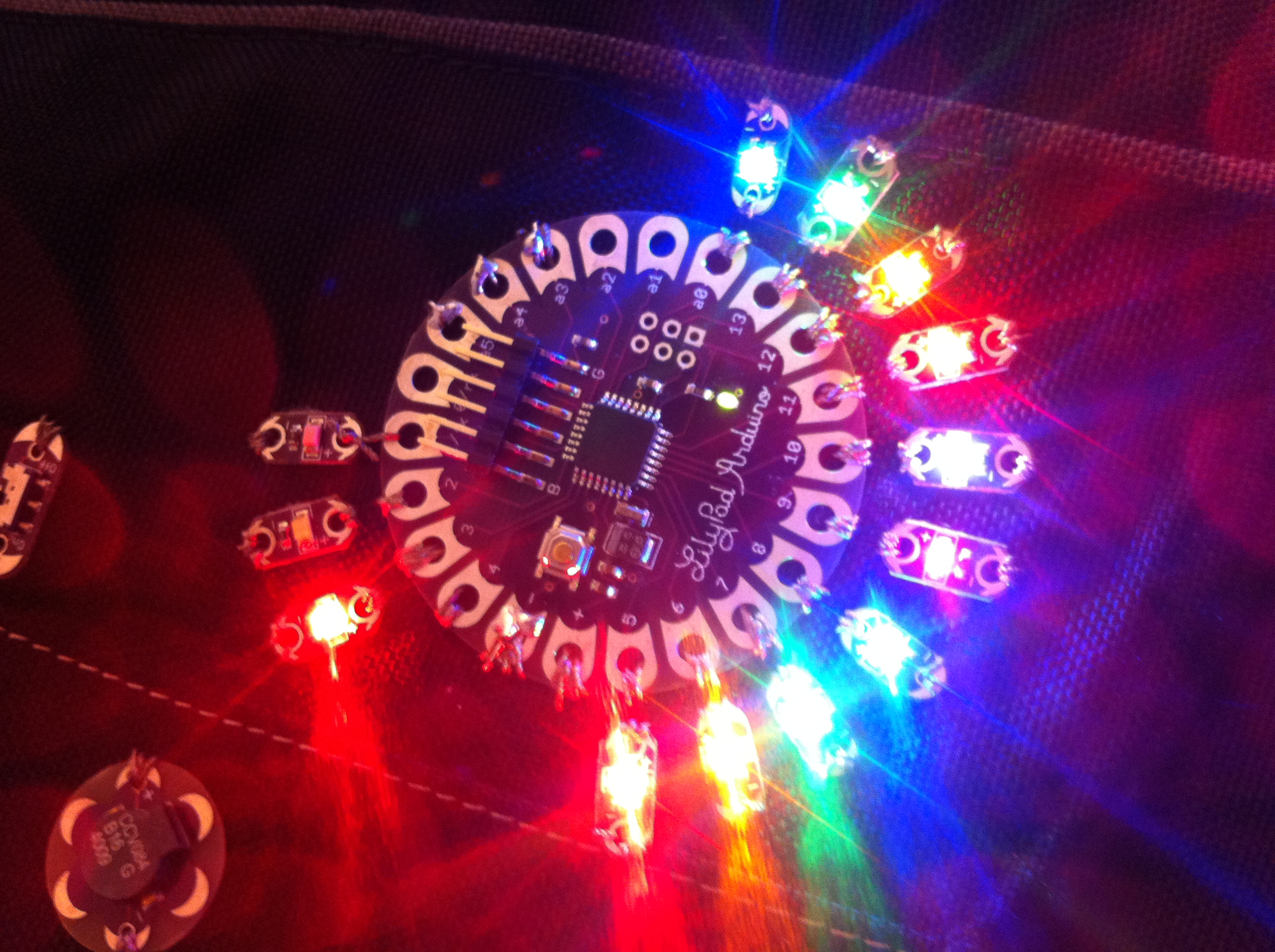
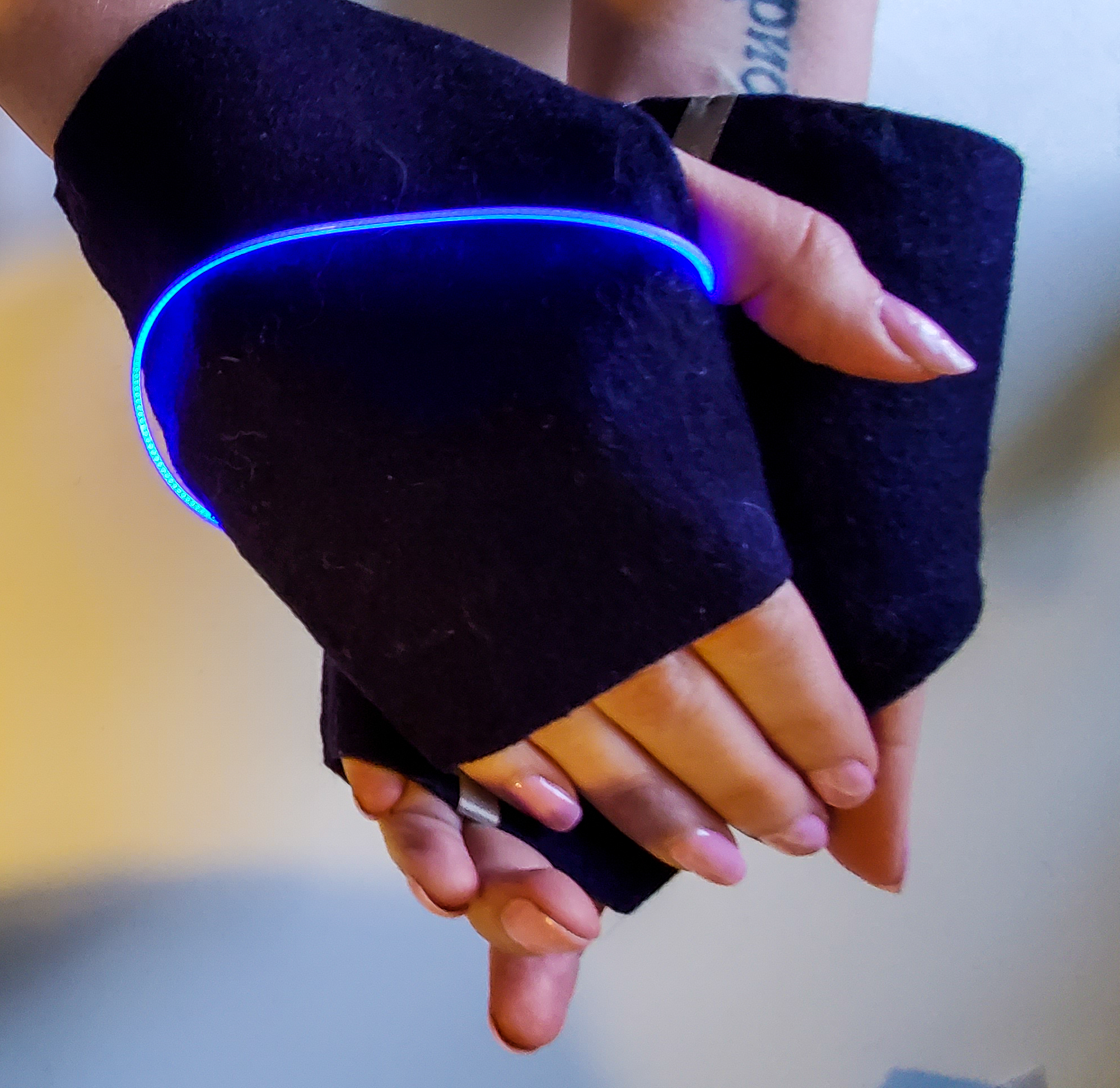
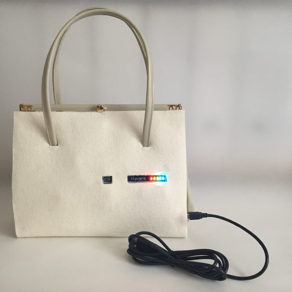
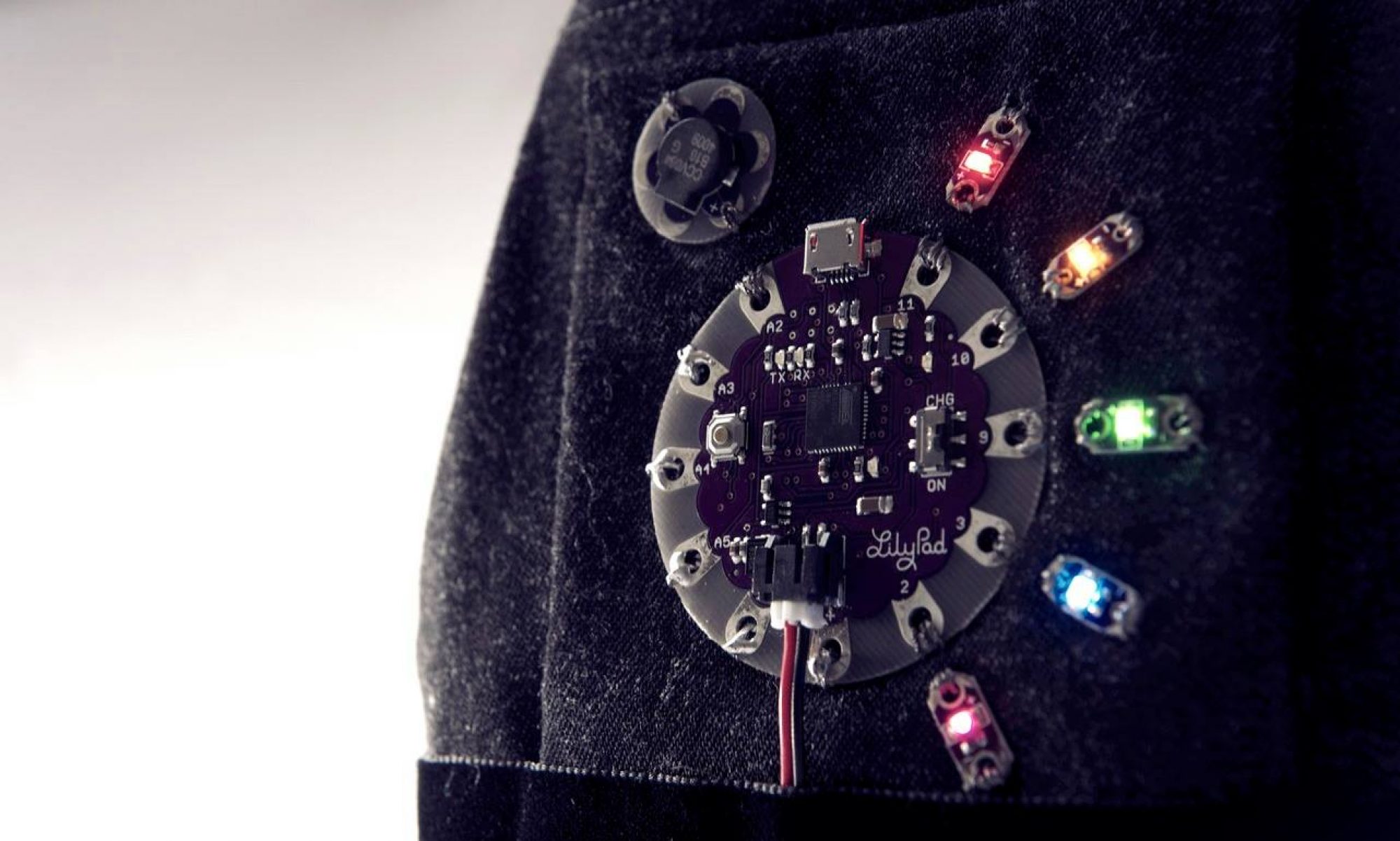
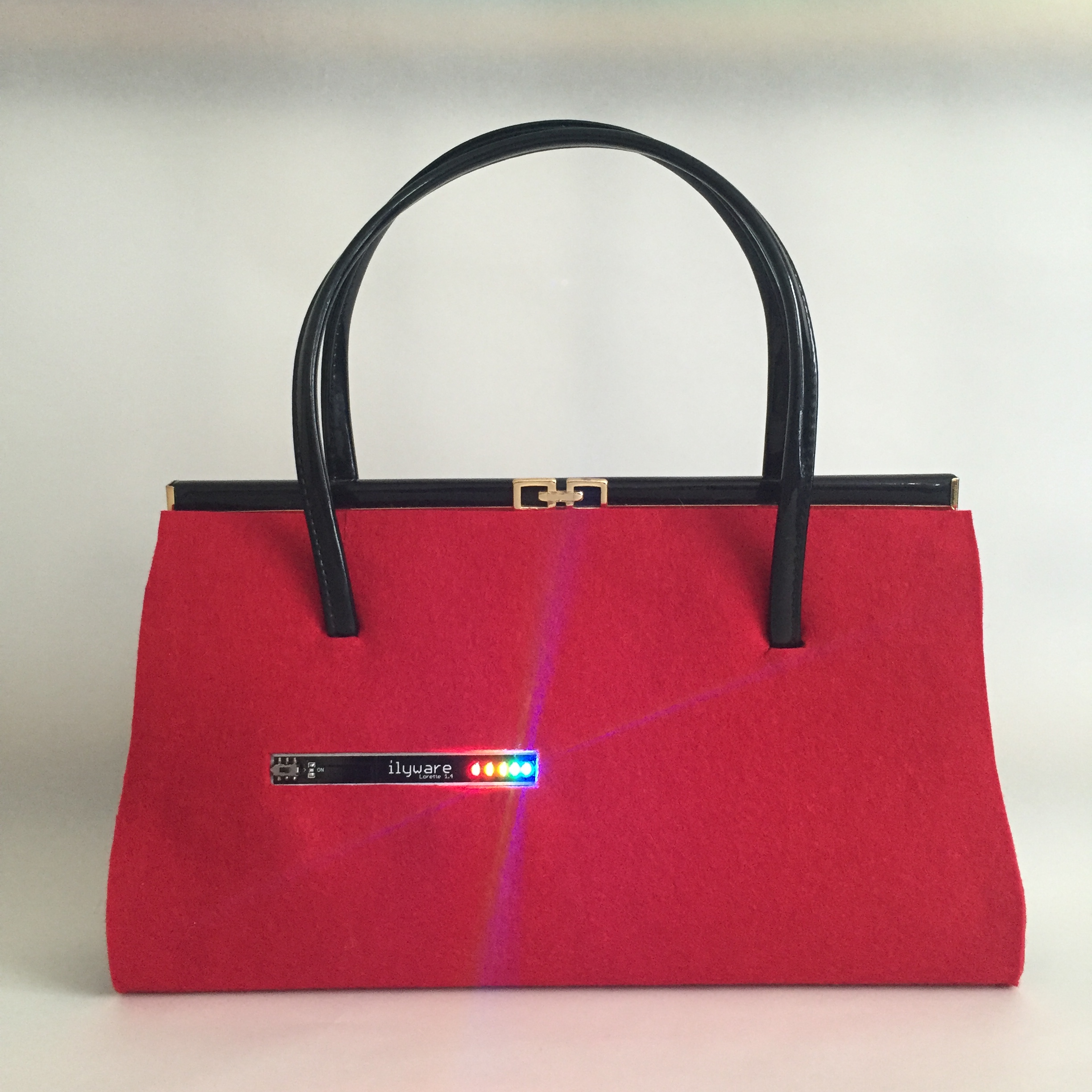
In Message Bag v2 there is no longer an LCD display and there is more emphasis on the LEDs for memory aids for the user. The initial reason for removing the screen was the pull on battery life, and also the ability to read the screen at a distance – say across a room, is a lot more difficult than a bright LED that can easily get the users attention from across the room.
If the LED is flashing then it is virtually impossible to ignore and will capture the user’s attention, that is a physiological reaction that has been used in stores to attract consumers attention before so we know this does work. Similar to the first prototype, we still use RFID technology with passive tags to record the items that are in the bag. Passive tags use the incident energy to both sense and communicate – they transmit their series of letters and numbers, and can be a little less accurate than active tags. A major advantage though is that they have a much lower cost, are small and they do not need a battery.
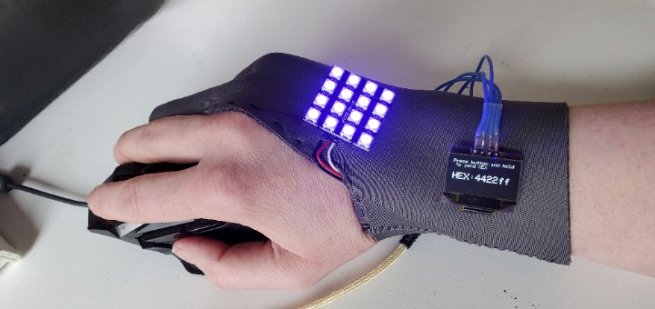
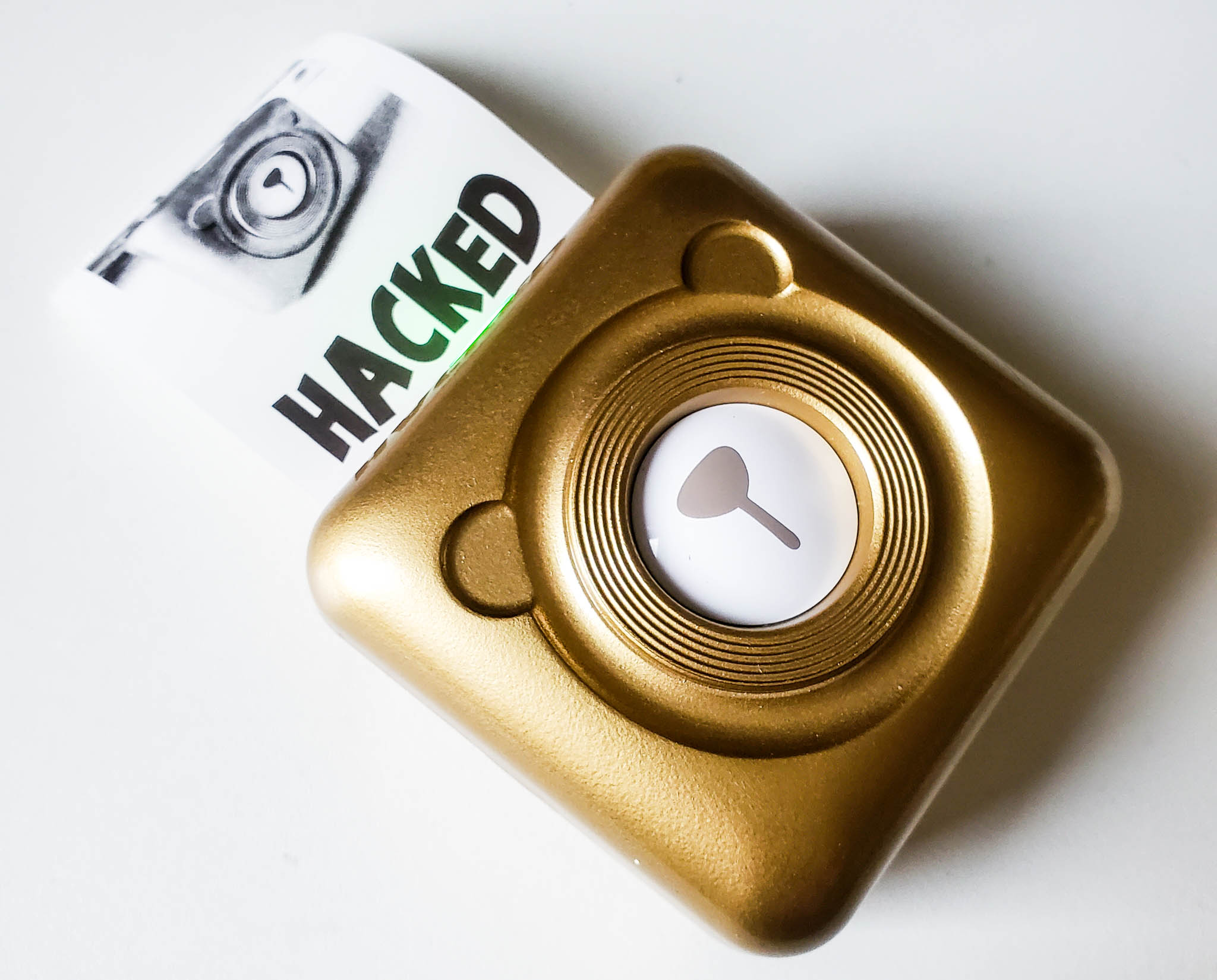
The first bag used an ID-12 reader, but as it is a little bulky and harder to secure in a wearable environment this was changed to an SLO18. This also has an integral antenna, but it is flat and has holes at the corners making it a lot easier to secure in a wearable item.
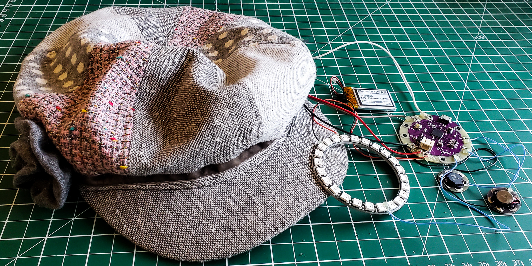
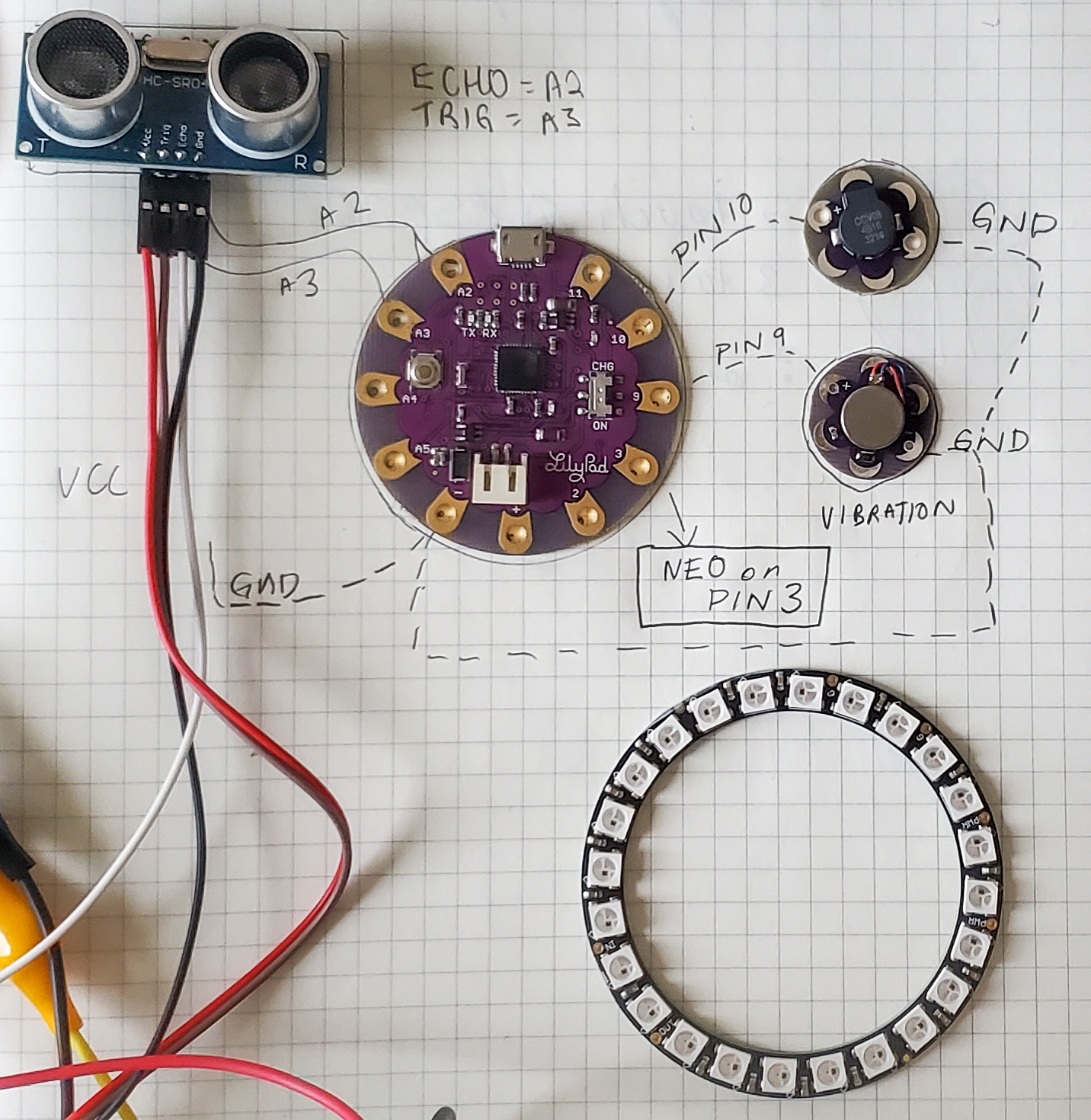
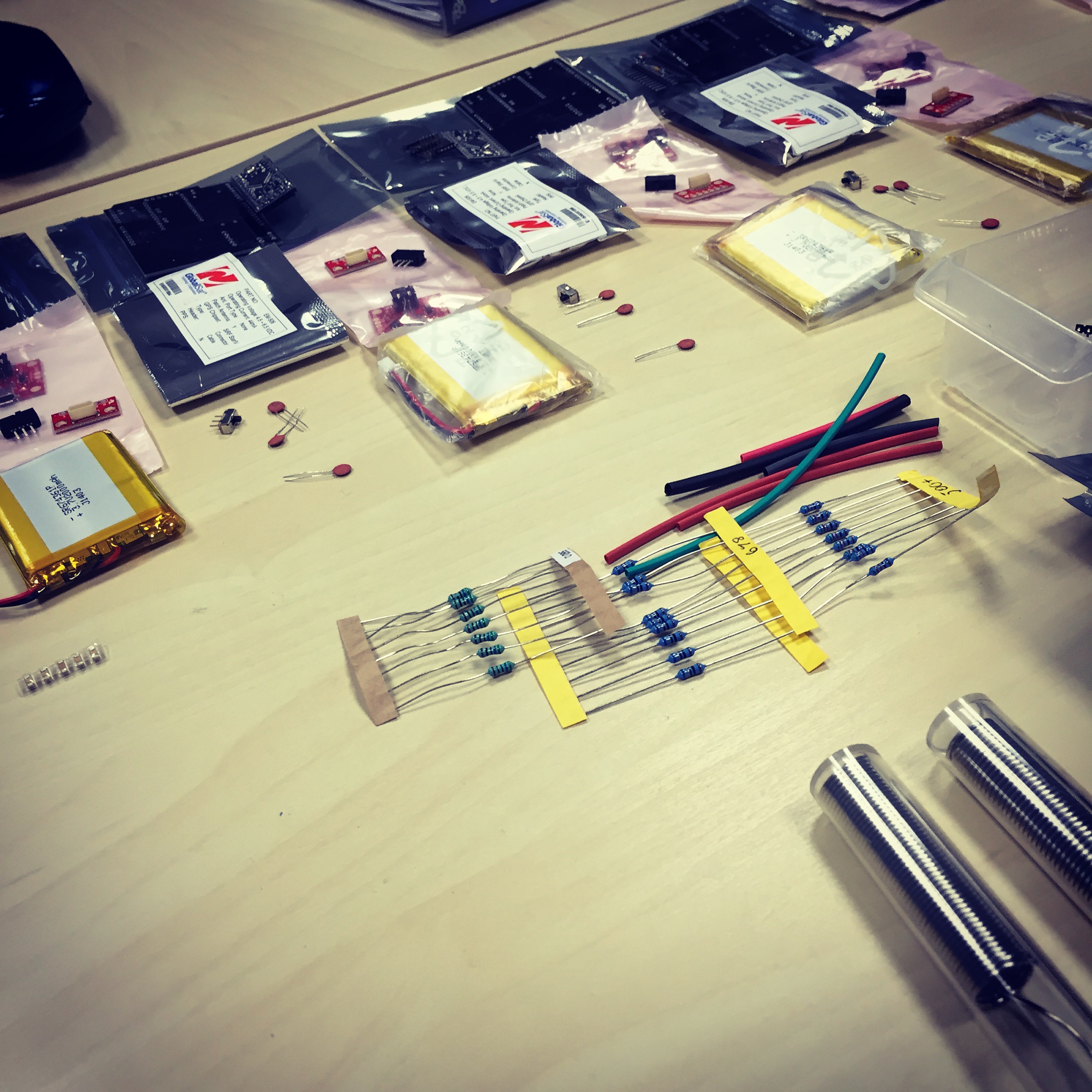
COMPONENTS
The components used are as follows:
Lily Pad Arduino 328 Main Board (I have also seen this board at CoolComponents for a lower price).
Lilypad Buzzer

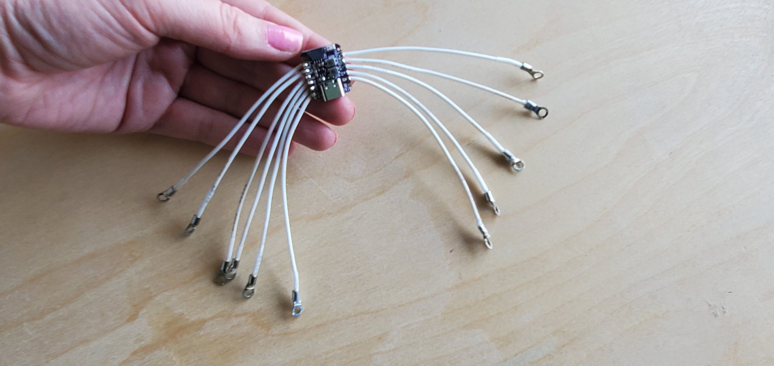
SL018 the implemented RFID reader, it is almost entirely flat and has 4 corners with holes in it so it can easily be sewn into the bag.
RFID 5V SL018 Stronglink purchased: http://www.skpang.co.uk/catalog/hf-rfid-module-sl018-5v-i2c-p-1081.html (5v) & Sample Code to get the board working initially http://marcboon.com/rfiduino/code/SL018/stronglink.pde and http://rfid.marcboon.com/#category2
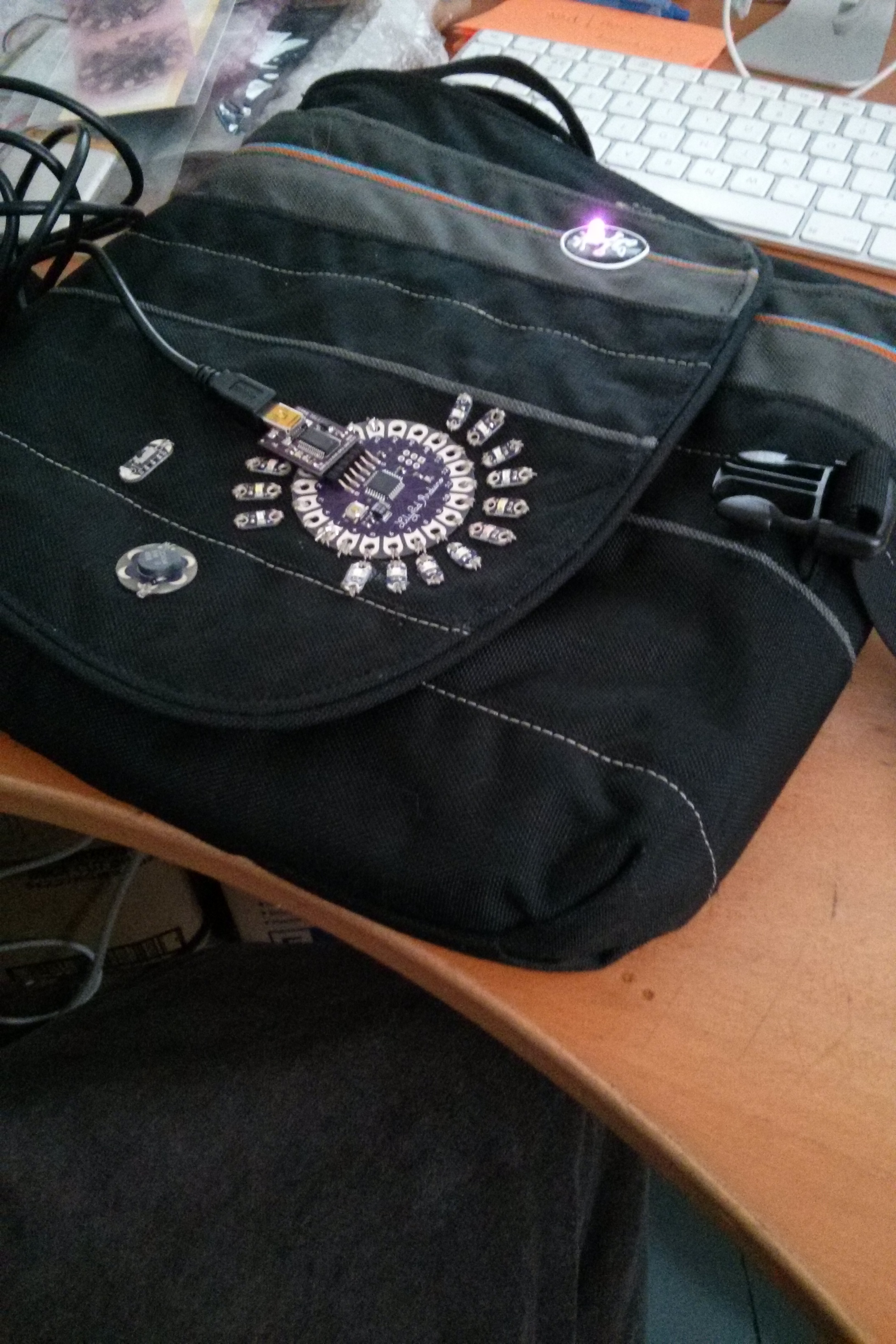
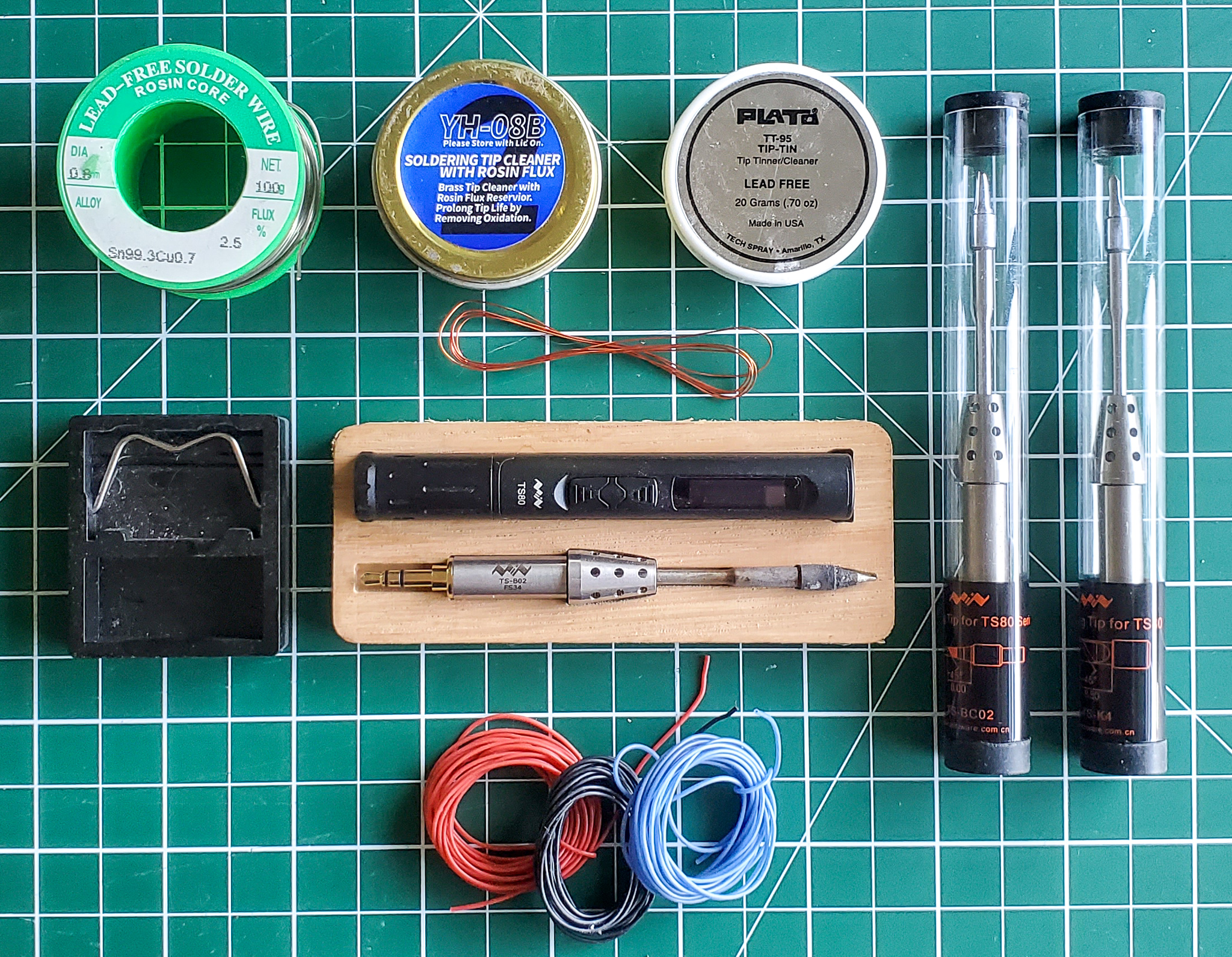
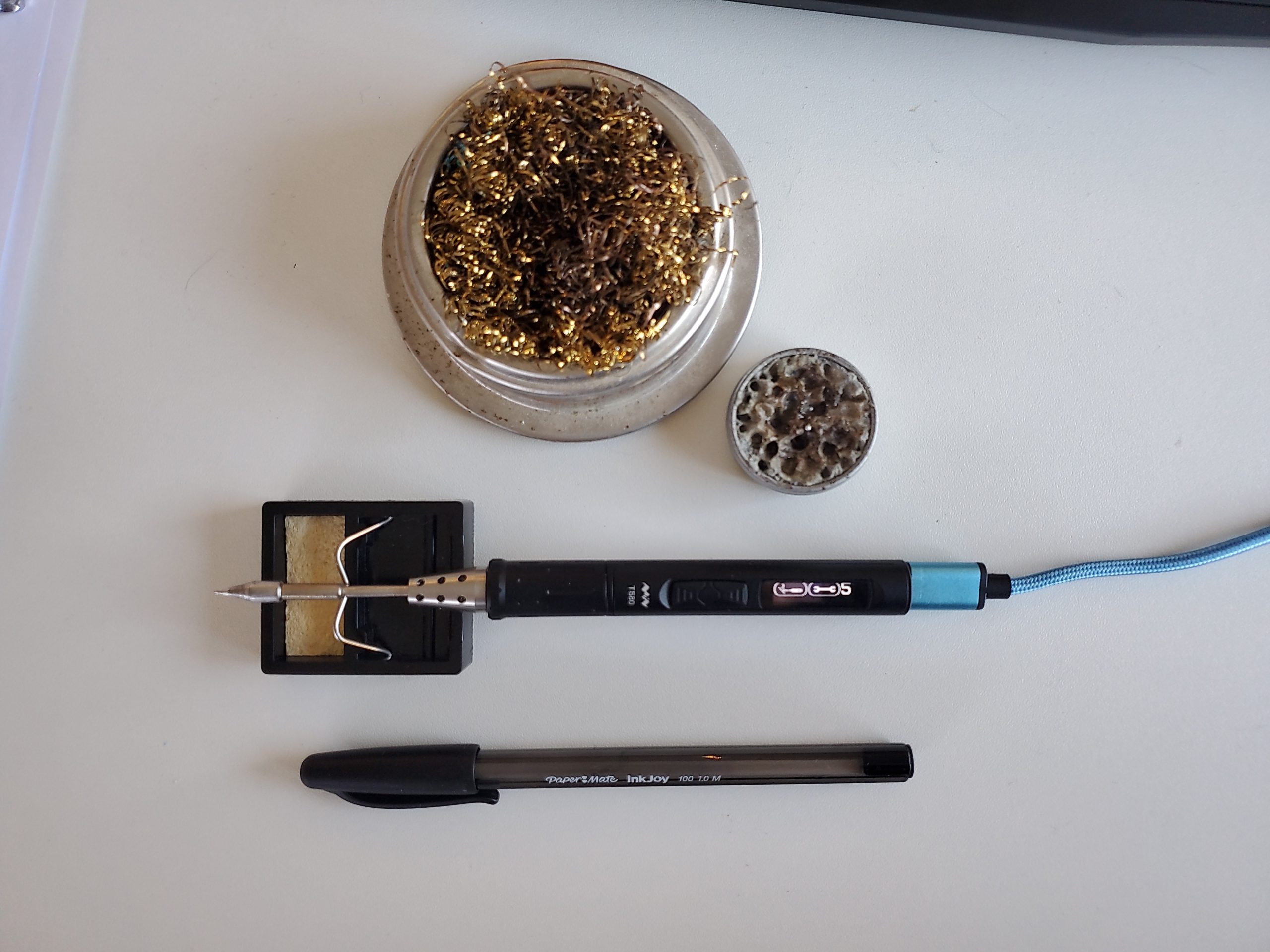
Using the FTDI to upload the Arduino code.
Micro cable used to connect the board to the computer to program the board – also needs an FTDI Basic Breakout 5V to connect it, that’s only needed to program the Lilypad, once you have your code on it, you remove the breakout and you can use it for other projects, so you only need one.
I used this USB LiIon/LiPoly charger for this project but have since found one also from SkPang to ease the order by going to one site for most of the components. (since then I also found a cheaper alternative at Hobbytronics)
Various LEDs
Slide Switch so they can turn off the bag
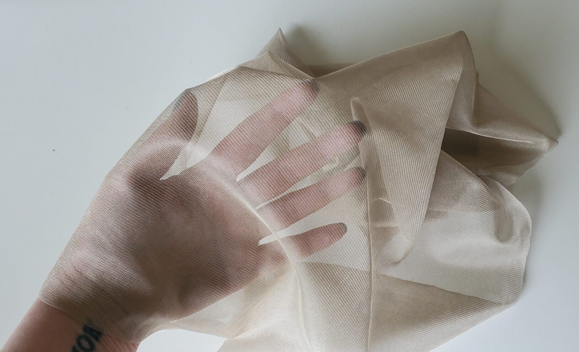
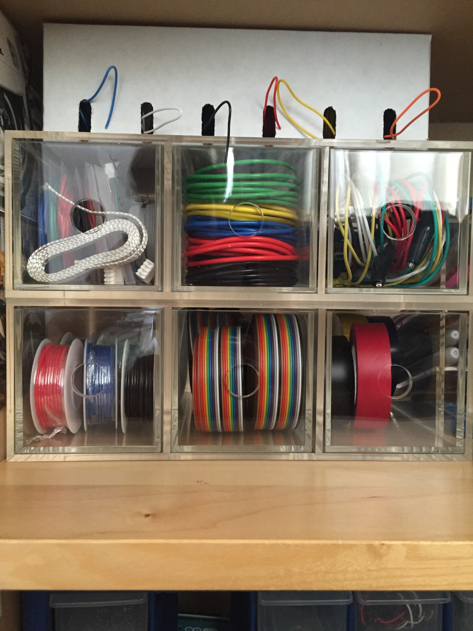
There is also various consumables, such as the thread used to sew the components to the bag and I also used multi core wire to wire in the RFID reader to the Lilypad, mostly because there was a possibility of a few wires overlapping which I didn’t want, I wanted a strong connection and I went multi over single core so that it would be more flexible in the material. Initially, when I was sewing the bag, the wire I used was really hard to sew, and frayed a lot and had a lot of resistance to the material making it time consuming to sew. I then found a 3 ply medium conductive thread which seems a little stiffer and slides through a lot easier. You also need a variety of tags to use with the bag.
OBSERVATIONS
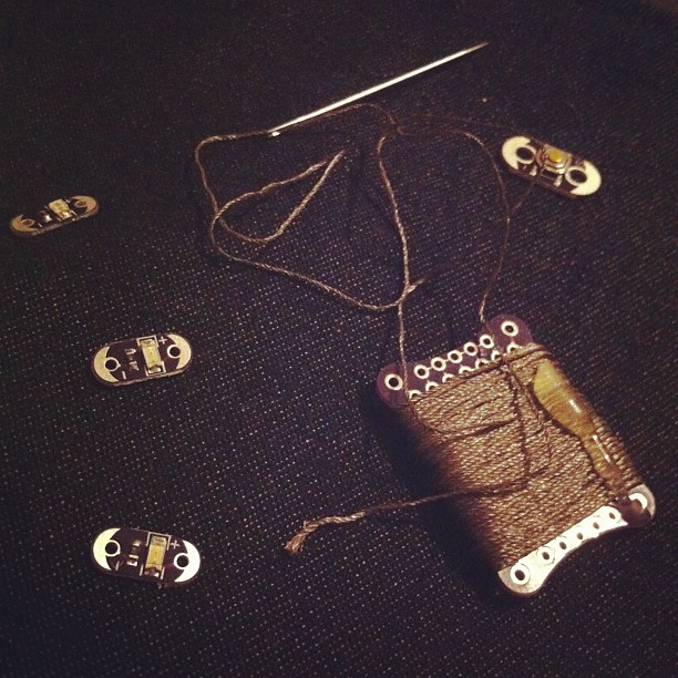
The first type of thread I used for the bag which I found more difficult to sew with.
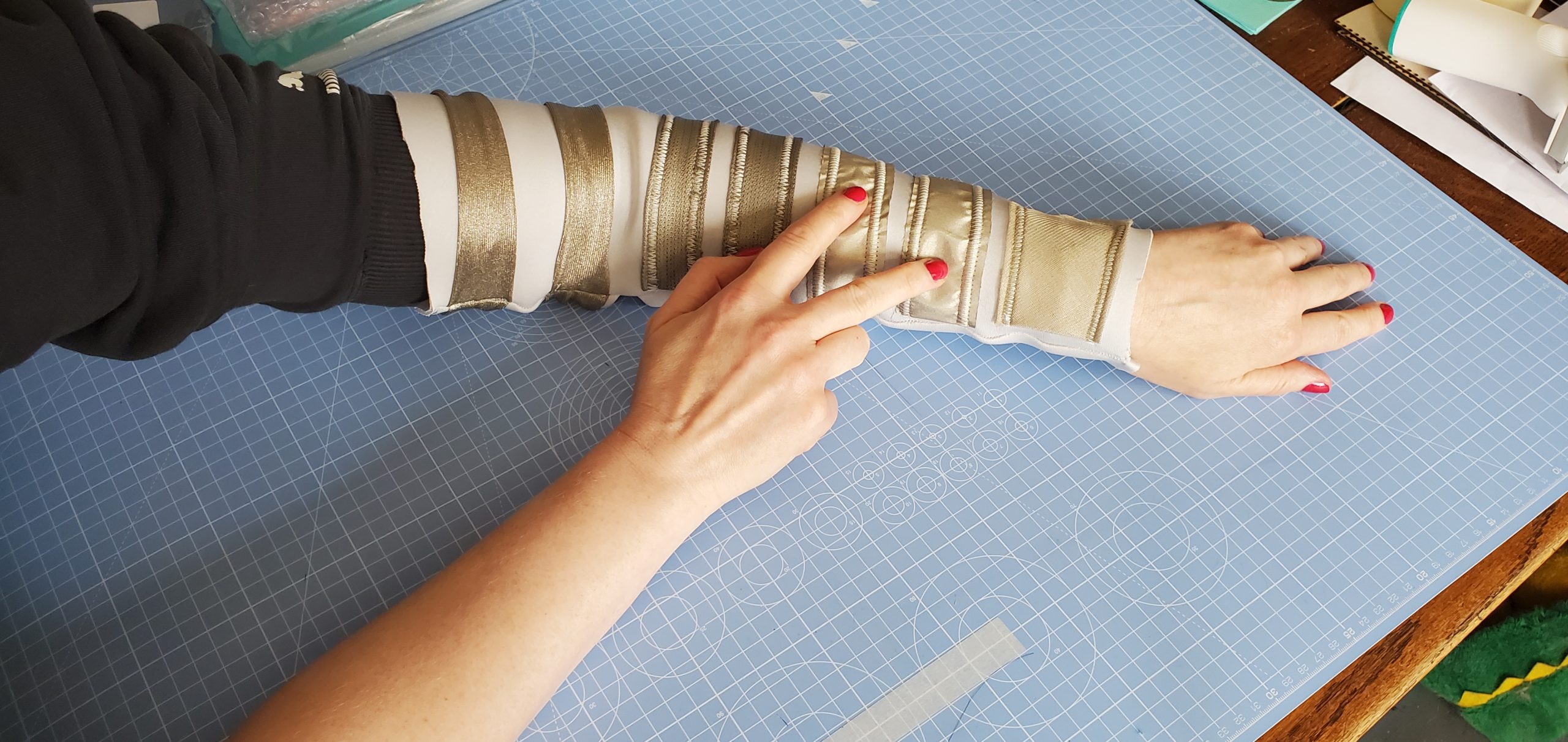
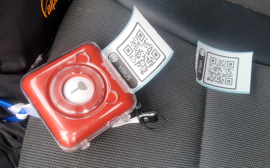
The components are small & discreet enough to go unnoticed in an obvious way when the bag is turned off. The bag was taken out in rain and the components did get wet, the surface of the components was covered in droplets but it had no effect. Additionally, because the sewing is done on the inside of the bag, the circuits themselves did not get exposed to water. The bag does have water resistant properties so the interior was always protected. No damage sustained and the components are described as able to be in water i.e. you can wash them if needs be.
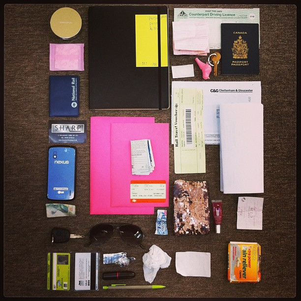
The objects that I was aiming to pack and remember, are packed without issue, but on one occasion, I wondered if I forgot my train tickets, and actually had forgotten my railcard and oyster – so these would need to be tagged as well. Part of the issue will be deciding which items to tag, and be sure that the items I find essential I have pre tagged. This will also be an issue when I come to prototype the next iteration of bags that will be used by testers, they will most likely at this stage have to tell me the objects they want to be programmed and it will have to be done before I issue them the bag. This isn’t ideal and will most likely need to be addressed in further bags.
Additionally, because I had forgotten my card, it would be handy to have a more persistent reminder as it nears the time that I need to leave, maybe the lights flash brighter if I have notified the bag that I have an appointment at 4pm and it knows I have still not packed my bag by 3.45 or similar. In keeping with that observation – can the bag notify me as I set my time of leaving? Do I type into the bag daily or weekly when I leave? Is there a more intuitive way to accomplish this? Can I somehow tell the bag what time I am leaving in the morning, maybe preprogrammed in some way, to say as it gets nearer the time and maybe I am more frantic with trying to get ready, that it has some kind of audible noise? Or maybe I record a voice message saying the items, and it plays this back closer to the time – and louder? Unless I dismiss the notification? Or each item has an audible reminder, and if the RFID is there that particular reminder isn’t played? So I would record my voice for each item? i.e. scan a tag – record my voice, and then each one is labelled alongside that item? What about turning it on in public to repack it – say at work? Can you lower the volume? or disable voice? Maybe the lights flash faster the more important? Is this a common cue? the flashing meaning ‘hurry up’?
There isn’t a low battery warning for a user, how will they know that the battery needs charging or is it a case that they plug it in every night?
They need to turn the bag on or off, will they remember to turn it on? Or to turn it off?
Also, a few times the switch for the single LED switched to on – this is not good as it may have potential embarrassment if it goes off in an environment that the user does not want it on, especially if it has the audio working and it is notifying you that items are packed.
Daily Use
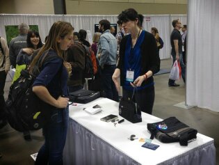
From using the bag on a daily basis, both during the week and weekends, at all variety of places and times (late evening shopping for groceries, going to teach an evening class, walking in the daytime in town, travelling on the train, the bus, the underground) it is difficult for people to remember all the lights connected to which items, this is very important as the hope is to reduce the cognitive load not increase it.
The next bag iteration will feature an LCD screen again, and a reduced amount of LEDs. I had comments about the bag in a few environments including a college where I was working a supply day and the students commented on the bag, ranging from thinking it was cool, the idea was cool, to some saying it’s cool but still looks a bit homemade… so there seems to be general social acceptance but some hesitation due to the fact it is actually ‘sewn’ on. As the prototypes get developed this is also getting more honed in and precise.
Something that came up in previous similar studies is that people noted that they would like some sort of weather notification so they also knew the context with which to pack their bag. This could be another future implementation to create a truly smart bag.
Websites for Components
Websites I have purchased these components from or the components are available:
[UK Sites]
http://proto-pic.co.uk/ don’t forget student discount if registered with your student account.
http://www.coolcomponents.co.uk/
http://www.skpang.co.uk/catalog/
http://www.mindsetsonline.co.uk/index.p … dium=email wearables mostly so good place for specialist
http://www.hobbytronics.co.uk/
[USA sites]